HEATING / AIR CONDITIONING AIR CONDITIONING SYSTEM No Cooling at All
DESCRIPTION
If cool air is not discharged (air is discharged), the following malfunctions are possible.
| Malfunction Status | Factor |
|---|---|
| Cool air is not discharged (air is discharged) (for Front) |
·
Cooler compressor assembly malfunction
·
Refrigerant pressure
·
Quantity of refrigerant gas lack
·
Dirty cooler condenser
·
Cooling fan system malfunction
·
A/M servo motor malfunction
·
Damper and link operation (jamming)
·
No. 1 cooler thermistor malfunction (determined as cold, conflicting with actual temperature)
·
Warm air flow |
| Malfunction Status | Factor |
|---|---|
| Cool air is not discharged (air is discharged) |
·
Cooler compressor assembly malfunction
·
Refrigerant pressure
·
Quantity of refrigerant gas lack
·
Dirty cooler condenser
·
Cooling fan system malfunction
·
No. 2 cooler thermistor malfunction (determined as cold, conflicting with actual temperature)
·
Rear magnetic calve circuit malfunction
·
Warm air flow |
| Malfunction Status | Factor |
|---|---|
| Cool air is not discharged (air is discharged) (for Rear (w/ Rear Cooler)) |
·
Cooler compressor assembly malfunction
·
Refrigerant pressure
·
Quantity of refrigerant gas lack
·
Dirty cooler condenser
·
Cooling fan system malfunction
·
A/M servo motor malfunction
·
Damper and link operation (jamming)
·
No. 2 cooler thermistor malfunction (determined as cold, conflicting with actual temperature)
·
Rear magnetic valve circuit malfunction
·
Warm air flow |
WIRING DIAGRAM
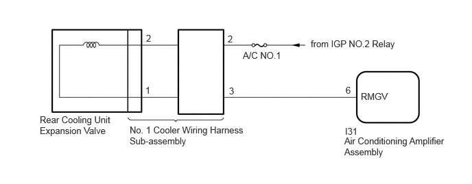
CAUTION / NOTICE / HINT
- NOTICE:
-
Inspect the fuses for circuits related to this system before performing the following inspection procedure.
PROCEDURE
- Result:
-
Result Proceed to for Front A for Rear (w/ Rear Cooler) B for Rear (w/ Rear Air Conditioning System) C
A
B
C
Operate each switch on the air conditioning control assembly and check that the switch indicators operate normally.
- OK:
-
All switch indicators operate normally.
- Result:
-
Proceed to OK NG
OK
NG
Perform the Active Test according to the display on the GTS.
- Body Electrical > Air Conditioner > Active Test
-
Tester Display Measurement Item Control Range Diagnostic Note Front Left Air Mix Damper Control Servo Motor No. 2 air conditioning radiator damper servo sub-assembly operation 128: Min
384: MaxOperates between 254 to 326 FL Air Mix Cool Damper Control Servo Motor No. 2 air conditioning radiator damper servo sub-assembly operation 128: Min
384: Maxfor Dual:Operates between 154 to 258
for 4 Zone:Operates between 254 to 358
Front Right Air Mix Damper Control Servo Motor No. 4 air conditioning radiator damper servo sub-assembly operation 128: Min
384: MaxOperates between 186 to 258 FR Air Mix Cool Damper Control Servo Motor No. 4 air conditioning radiator damper servo sub-assembly operation 128: Min
384: MaxOperates between 154 to 258 Fr Control RL Air Mix Damper Control Servo Motor No. 2 air conditioning radiator damper servo sub-assembly operation 128: Min
384: MaxOperates between 154 to 258 Fr Control RR Air Mix Damper Control Servo Motor No. 4 air conditioning radiator damper servo sub-assembly operation 128: Min
384: MaxOperates between 154 to 258
- Body Electrical > Air Conditioner > Active Test
-
Tester Display Front Left Air Mix Damper Control Servo Motor - 50004 450 26 201
- Body Electrical > Air Conditioner > Active Test
-
Tester Display FL Air Mix Cool Damper Control Servo Motor - 50004 450 27
- Body Electrical > Air Conditioner > Active Test
-
Tester Display Front Right Air Mix Damper Control Servo Motor - 50004 450 28 205
- Body Electrical > Air Conditioner > Active Test
-
Tester Display FR Air Mix Cool Damper Control Servo Motor - 50004 450 29
- Body Electrical > Air Conditioner > Active Test
-
Tester Display Fr Control RL Air Mix Damper Control Servo Motor - 50004 450 36
- Body Electrical > Air Conditioner > Active Test
-
Tester Display Fr Control RR Air Mix Damper Control Servo Motor - 50004 450 37
- OK:
-
Damper servo motor is operated.
- Result:
-
Proceed to OK NG
OK
Click hereVehicle Interior>HEATING / AIR CONDITIONING>REFRIGERANT (for HFC-134a(R134a))>ON-VEHICLE INSPECTION
NG
Click hereVehicle Interior>HEATING / AIR CONDITIONING>AIR CONDITIONING SYSTEM>DIAGNOSTIC TROUBLE CODE CHART
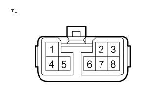
| *a | Front view of wire harness connector (to No. 1 Cooler Wiring Harness Sub-assembly) |
Disconnect the No. 1 cooler wiring harness sub- assembly connector.
Measure the voltage according to the value(s) in the table below.
- Standard Voltage:
-
Tester Connection Switch Condition Specified Condition 2 - Body ground Ignition switch off Below 1 V 2 - Body ground Ignition switch ON 11 to 14 V
- Result:
-
Proceed to OK NG
OK
NG
Disconnect the No. 1 wiring air conditioning harness sub-assembly connector.
Disconnect the I31 air conditioning amplifier assembly connector.
Measure the resistance according to the value(s) in the table below.
- Standard Resistance:
-
Tester Connection Condition Specified Condition Click Location & Routing(I31)Location & Routingewd_type=routing;type=c;code=I31
3 - I31-6(RMGV) Always Below 1 Ω 3 or I31-6(RMGV) - Other terminals and body ground Always 10 kΩ or higher
- Result:
-
Proceed to OK NG
OK
NG
Replace the rear cooling unit expansion valve with a new or known good one and check that the condition returns to normal.
Click hereVehicle Interior>HEATING / AIR CONDITIONING>REAR AIR CONDITIONING UNIT>DISASSEMBLY
- HINT:
-
Since the rear cooling unit expansion valve cannot be inspected while it is removed from the vehicle, replace the rear cooling unit expansion valve with a new or known good one and check that the condition returns to normal.
- OK:
-
Same problem does not occur.
- Result:
-
Proceed to OK NG
OK
NG
Replace the No. 1 cooler wiring harness sub-assembly with a new or known good one and check that the condition returns to normal.
- OK:
-
Same problem does not occur.
- Result:
-
Proceed to OK NG
OK
NG
Click hereVehicle Interior>HEATING / AIR CONDITIONING>REFRIGERANT (for HFC-134a(R134a))>ON-VEHICLE INSPECTION
| *a | Front view of wire harness connector (to No. 1 Cooler Wiring Harness Sub-assembly) |
Disconnect the wiring air conditioning harness sub- assembly connector.
Measure the voltage according to the value(s) in the table below.
- Standard Voltage:
-
Tester Connection Switch Condition Specified Condition 2 - Body ground Ignition switch off Below 1 V 2 - Body ground Ignition switch ON 11 to 14 V
- Result:
-
Proceed to OK NG
OK
NG
Disconnect the No. 1 wiring air conditioning harness sub-assembly connector.
Disconnect the I31 air conditioning amplifier assembly connector.
Measure the resistance according to the value(s) in the table below.
- Standard Resistance:
-
Tester Connection Condition Specified Condition Click Location & Routing(I31)Location & Routingewd_type=routing;type=c;code=I31
3 - I31-6(RMGV) Always Below 1 Ω 3 or I31-6(RMGV) - Other terminals and body ground Always 10 kΩ or higher
- Result:
-
Proceed to OK NG
OK
NG
Replace the rear cooling unit expansion valve with a new or known good one and check that the condition returns to normal.
Click hereVehicle Interior>HEATING / AIR CONDITIONING>REAR AIR CONDITIONING UNIT>DISASSEMBLY
- HINT:
-
Since the rear cooling unit expansion valve cannot be inspected while it is removed from the vehicle, replace the rear cooling unit expansion valve with a new or known good one and check that the condition returns to normal.
- OK:
-
Same problem does not occur.
- Result:
-
Proceed to OK NG
OK
NG
Replace the No. 2 cooler wiring harness sub-assembly with a new or known good one and check that the condition returns to normal.
- OK:
-
Same problem does not occur.
- Result:
-
Proceed to OK NG
OK
NG
Perform the Active Test according to the display on the GTS.
- Body Electrical > Air Conditioner > Active Test
-
Tester Display Measurement Item Control Range Diagnostic Note Rear Left Air Mix Damper Control Servo Motor Rear air mix damper servo sub-assembly operation Min.: 128
Max.: 384Operates between 254 to 299 pulses Rear Right Air Mix Damper Control Servo Motor No. 2 rear air mix damper servo sub-assembly operation Min.: 128
Max.: 384Operates between 213 to 258 pulses Rear Air Outlet Damper Control Servo Motor Rear mode damper servo sub-assembly operation Min.: 128
Max.: 384Operates between 200 to 276 pulses
- Body Electrical > Air Conditioner > Active Test
-
Tester Display Rear Left Air Mix Damper Control Servo Motor - 50004 450 42
- Body Electrical > Air Conditioner > Active Test
-
Tester Display Rear Right Air Mix Damper Control Servo Motor - 50004 450 43
- Body Electrical > Air Conditioner > Active Test
-
Tester Display Rear Air Outlet Damper Control Servo Motor - 50004 450 51
- OK:
-
Damper servo motor is operated.
- Result:
-
Proceed to OK NG
OK
Click hereVehicle Interior>HEATING / AIR CONDITIONING>REFRIGERANT (for HFC-134a(R134a))>ON-VEHICLE INSPECTION
NG
Click hereVehicle Interior>HEATING / AIR CONDITIONING>AIR CONDITIONING SYSTEM>DIAGNOSTIC TROUBLE CODE CHART