HEATING / AIR CONDITIONING HEATER WATER PUMP INSTALLATION
CAUTION / NOTICE / HINT
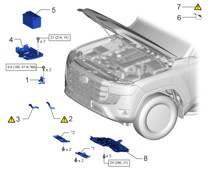
| Procedure | Part Name Code |

|

|

|
|
|---|---|---|---|---|---|
| 1 | HEATER ACCESSORY ASSEMBLY | 87200D | - | - | - |
| 2 | INLET HEATER WATER HOSE B | 87245B | ( ) |
- | - |
| 3 | OUTLET HEATER WATER HOSE B | 87246B | () |
- | - |
| 4 | BATTERY CARRIER ASSEMBLY | 74410 | - | - | - |
| 5 | BATTERY | 28800 | - | - | - |
| 6 | ADD ENGINE COOLANT | - | - | () |
- |
| 7 | INSPECT FOR COOLANT LEAK | - | () |
- | - |
| 8 | NO. 1 ENGINE UNDER COVER ASSEMBLY | 51410 | - | - | - |
| *1 | ENGINE SIDE COVER SUB-ASSEMBLY LH | *2 | ENGINE SIDE COVER SUB-ASSEMBLY RH |

|
N*m (kgf*cm, ft.*lbf): Specified torque | - | - |
CAUTION / NOTICE / HINT
- HINT:
-
A bolt without a torque specification is shown in the standard bolt chart.
-
Click hereGeneral>SPECIFICATIONS>STANDARD BOLT>SPECIFIED TORQUE FOR STANDARD BOLTS
PROCEDURE

 87200D 1.INSTALL HEATER ACCESSORY ASSEMBLY
- Torque:
- 9.8 N*m (100 kgf*cm, 87 in.*lbf)
87245B 2.CONNECT INLET HEATER WATER HOSE B
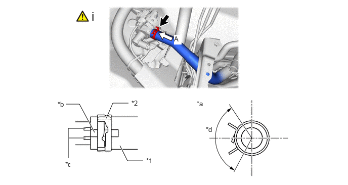
| *1 | Inlet Heater Water Hose B | *2 | Hose Clip |
| *a | View A | *b | Marking |
| *c | Positioning Rib | *d | Hose Clip Installation Angle (120° From Above the Vehicle) |
Align the marking of the inlet heater water hose B with the positioning rib of the heater accessory assembly and connect the inlet heater water hose B.
- NOTICE:
-
Do not apply excessive force to the inlet heater water hose B.
87246B 3.CONNECT OUTLET HEATER WATER HOSE B
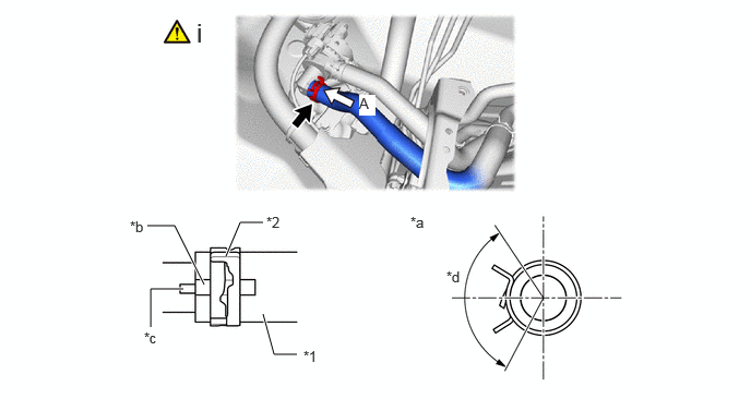
| *1 | Outlet Heater Water Hose B | *2 | Hose Clip |
| *a | View A | *b | Marking |
| *c | Positioning Rib | *d | Hose Clip Installation Angle (120° From Above the Vehicle) |
Align the marking of the outlet heater water hose B with the positioning rib of the heater accessory assembly and connect the outlet heater water hose B.
- NOTICE:
-
Do not apply excessive force to the outlet heater water hose B.
74410 4.INSTALL BATTERY CARRIER ASSEMBLY
- Torque:
- 21 N*m (214 kgf*cm, 15 ft.*lbf)
28800 5.INSTALL BATTERY
6.ADD ENGINE COOLANT
7.INSPECT FOR COOLANT LEAK
51410 8.INSTALL NO. 1 ENGINE UNDER COVER ASSEMBLY