INTERIOR PANELS / TRIM FRONT CONSOLE BOX(w/ Cool Box) REASSEMBLY
CAUTION / NOTICE / HINT
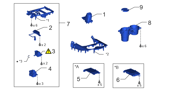
| Procedure | Part Name Code |

|

|

|
|
|---|---|---|---|---|---|
| 1 | SHIFTING HOLE COVER SUB-ASSEMBLY | 58808 | - | - | - |
| 2 | SHIFT POSITION INDICATOR | 35978 | - | - | - |
| 3 | ELECTRIC PARKING BRAKE SWITCH ASSEMBLY | 84390B | ( ) |
- | - |
| 4 | TRANSFER POSITION SWITCH | 84223A | - | - | - |
| 5 | CONSOLE BOX POCKET | 58825A | - | - | - |
| 6 | MOBILE WIRELESS CHARGER CRADLE ASSEMBLY | 861C0 | - | - | - |
| 7 | INTEGRATION CONTROL ASSEMBLY | 840C0A | - | - | - |
| 8 | CONSOLE CUP HOLDER BOX SUB-ASSEMBLY | 58803C | - | - | - |
| 9 | CUP HOLDER HOLE COVER | 55619E | - | - | - |
| *A | w/o Wireless Charger | *B | w/ Wireless Charger |
| *1 | SHIFTING HOLE BEZEL | *2 | UPPER CONSOLE PANEL SUB-ASSEMBLY |
| *3 | CABLE TIE | - | - |
| ● | Non-reusable part | - | - |
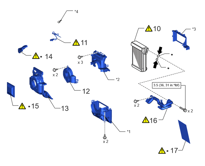
| Procedure | Part Name Code |
|
|
|
|
|---|---|---|---|---|---|
| 10 | COOLER (COOL BOX) EVAPORATOR SUB-ASSEMBLY | 88501E | () |
- | - |
| 11 | NO. 2 COOLER THERMISTOR | 88625E | () |
- | - |
| 12 | COOL BOX BLOWER MOTOR WITH FAN SUB-ASSEMBLY | 87103F | - | - | - |
| 13 | NO. 5 COOLING BOX PACKING | - | - | - | - |
| 14 | NO. 2 COOLING BOX PACKING | 87429D | () |
- | - |
| 15 | NO. 3 COOLING BOX PACKING | 87429E | () |
- | - |
| 16 | NO. 1 COOLING BOX TUBE AND ACCESSORY ASSEMBLY | 88710X | () |
- | - |
| 17 | NO. 1 COOLING BOX PACKING | 87429C | () |
- | - |
| *1 | LOWER COOLING UNIT CASE | *2 | FRONT COOLING UNIT CASE |
| *3 | REAR COOLING UNIT CASE | *4 | CLAMP |

|
N*m (kgf*cm, ft.*lbf): Specified torque | ● | Non-reusable part |

|
Compressor oil ND-OIL 8 or equivalent | - | - |
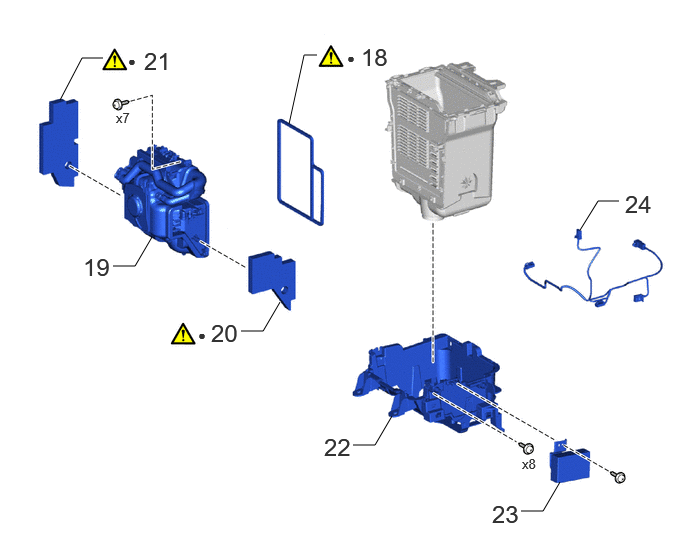
| Procedure | Part Name Code |
|
|
|
|
|---|---|---|---|---|---|
| 18 | NO. 4 COOLING BOX PACKING | 87429F | () |
- | - |
| 19 | NO. 2 COOLING BOX ASSEMBLY | 88530A | - | - | - |
| 20 | INNER NO. 1 COOLER DUCT INSULATOR LH | 63945 | () |
- | - |
| 21 | INNER NO. 1 COOLER DUCT INSULATOR RH | 63935 | () |
- | - |
| 22 | CONSOLE COMPARTMENT BOX | - | - | - | - |
| 23 | COOLING BOX AMPLIFIER ASSEMBLY | - | - | - | - |
| 24 | AIR CONDITIONER HARNESS | - | - | - | - |
| ● | Non-reusable part | - | - |
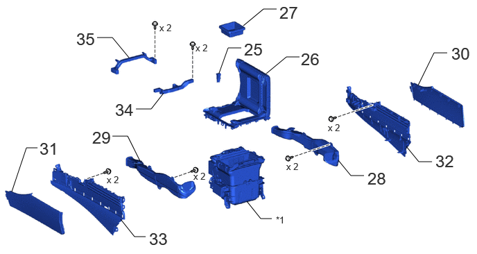
| Procedure | Part Name Code |
|
|
|
|
|---|---|---|---|---|---|
| 25 | CONTROL SWITCH ASSEMBLY | 88610S | - | - | - |
| 26 | COOL BOX CONSOLE COMPARTMENT DOOR SUB-ASSEMBLY | 58905B | - | - | - |
| 27 | LOWER CONSOLE BOX POCKET | 58826B | - | - | - |
| 28 | NO. 1 CONSOLE BOX DUCT | 58861B | - | - | - |
| 29 | NO. 2 CONSOLE BOX DUCT | 58862B | - | - | - |
| 30 | FRONT NO. 1 CONSOLE BOX INSERT | 58816F | - | - | - |
| 31 | FRONT NO. 2 CONSOLE BOX INSERT | 58817C | - | - | - |
| 32 | NO. 1 COOL BOX BOX PANEL | 58911C | - | - | - |
| 33 | NO. 2 COOL BOX BOX PANEL | 58912F | - | - | - |
| 34 | NO. 2 COOL BOX RETAINER | 58987C | |||
| 35 | NO. 1 COOL BOX RETAINER | 58985E | |||
| *1 | NO. 2 COOLING BOX ASSEMBLY | - | - |
CAUTION / NOTICE / HINT
- HINT:
-
·
Use the same procedure for RHD and LHD vehicles.
·The procedure listed below is for LHD vehicles.
PROCEDURE

 58808 1.INSTALL SHIFTING HOLE COVER SUB-ASSEMBLY
35978 2.INSTALL SHIFT POSITION INDICATOR
84390B 3.INSTALL ELECTRIC PARKING BRAKE SWITCH ASSEMBLY
|
|
() |
84223A 4.INSTALL TRANSFER POSITION SWITCH
58825B 5.INSTALL CONSOLE BOX POCKET (w/o Wireless Charger)
861C0 6.INSTALL MOBILE WIRELESS CHARGER CRADLE ASSEMBLY (w/ Wireless Charger)
840C0A 7.INSTALL INTEGRATION CONTROL ASSEMBLY
58803C 8.INSTALL CONSOLE CUP HOLDER BOX SUB-ASSEMBLY
55619E 9.INSTALL CUP HOLDER HOLE COVER
88501E 10.INSTALL COOLER (COOL BOX) EVAPORATOR SUB-ASSEMBLY
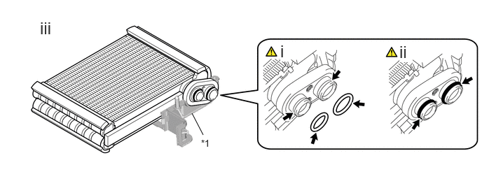
| *1 | Rear Cooling Unit Case | - | - |
Remove the vinyl tape from the cooler (cool box) evaporator sub-assembly and then apply a sufficient amount of compressor oil to 2 new O-rings and the fitting surface with the cooler (cool box) evaporator sub-assembly.
- Compressor Oil:
-
ND-OIL 8 or equivalent
Install the 2 O-rings to the cooler (cool box) evaporator sub-assembly.
- NOTICE:
-
Keep the O-rings and O-ring fitting surfaces free of foreign matter.
Install the cooler (cool box) evaporator sub-assembly to the rear cooling unit case.
88625A 11.INSTALL NO. 2 COOLER THERMISTOR
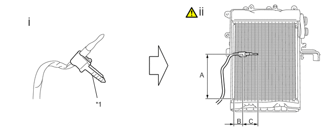
| *1 | Clamp | - | - |
Install the clamp.
Install the No. 2 cooler thermistor as shown in the illustration.
- Installation Position:
-
Part Length A 85 to 95 mm (3.35 to 3.74 in.) B 15.9 mm (0.63 in.)(3 Fins) C 26 mm (1.02 in.)
- NOTICE:
-
·
Be sure to insert the No. 2 cooler thermistor only once because reinserting it into the same position will not allow it to be firmly secured.
·After inserting the No. 2 cooler thermistor, do not apply excessive force to the wire.
·When reusing the cooler (cool box) evaporator sub-assembly, insert the sensor part of the No. 2 cooler thermistor one row from the row that had been used previously.
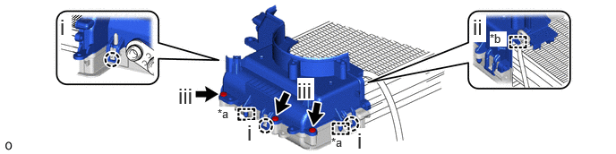
| *a | Guide | *b | Clamp |
Attach the guide and claw and install the front cooling unit case.
Attach the clamp.
Install the 3 screws.
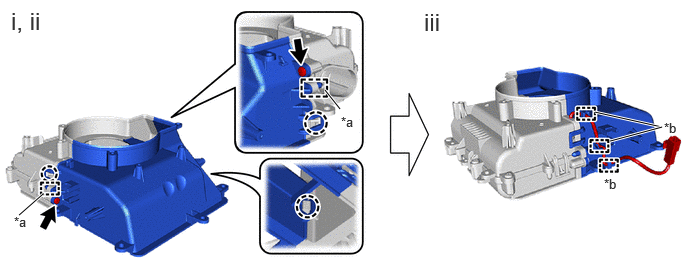
| *a | Guide | *b | Clamp |
Attach the guide and claw and install the lower cooling unit case.
Install the 2 screws.
Attach the clamp.
87103F 12.INSTALL COOL BOX BLOWER MOTOR WITH FAN SUB-ASSEMBLY
13.INSTALL NO. 5 COOLING BOX PACKING
87429D 14.INSTALL NO. 2 COOLING BOX PACKING

Install a new No. 2 cooling box packing.
- NOTICE:
-
Completely remove the remaining No. 2 cooling box packing from the attachment surface during removal.
87429E 15.INSTALL NO. 3 COOLING BOX PACKING
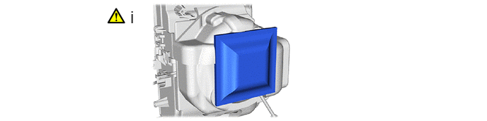
Install a new No. 3 cooling box packing.
- NOTICE:
-
Completely remove the remaining No. 3 cooling box packing from the attachment surface during removal.
88710X 16.INSTALL NO. 1 COOLING BOX TUBE AND ACCESSORY ASSEMBLY
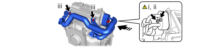
| *a | Protective Covering on the Pipes | - | - |

|
Install in this Direction | - | - |
Remove the vinyl tape from the No. 1 cooling box tube and accessory assembly.
Using a 5 mm hexagon socket wrench, install the No. 1 cooling box tube and accessory assembly with the 2 hexagon bolts.
- Torque:
- 3.5 N*m (36 kgf*cm, 31 in.*lbf)
- NOTICE:
-
Make sure not to cut the O-ring while installing it. (Cut O-rings cannot be installed.)
- HINT:
-
·
Slide back the protective covering on the pipe when installing the hexagon bolt.
·Return the protective covering on the pipe to its original position after installing the hexagon bolt.
Install the 2 screws.
87429C 17.INSTALL NO. 1 COOLING BOX PACKING

| *1 | Case | - | - |
| *a | Overlap Position | - | - |
Attach the No. 1 cooling box packing as shown in the illustration so that the pipes are not exposed.
- NOTICE:
-
·
Completely remove the remaining No. 1 cooling box packing from the attachment surface during removal.
·Attach the packing so that there are no gaps between it and the case.
87429F 18.INSTALL NO. 4 COOLING BOX PACKING

Install a new No. 4 cooling box packing.
- NOTICE:
-
Completely remove the remaining No. 4 cooling box packing from the attachment surface during removal.
88530A 19.INSTALL NO. 2 COOLING BOX ASSEMBLY
63945 20.INSTALL INNER NO. 1 COOLER DUCT INSULATOR LH

Install a new inner No. 1 cooler duct insulator LH.
- NOTICE:
-
Completely remove the remaining inner No. 1 cooler duct insulator LH from the attachment surface during removal.
63935 21.INSTALL INNER NO. 1 COOLER DUCT INSULATOR RH

Install a new inner No. 1 cooler duct insulator RH.
- NOTICE:
-
Completely remove the remaining inner No. 1 cooler duct insulator RH from the attachment surface during removal.
22.INSTALL CONSOLE COMPARTMENT BOX
23.INSTALL COOLING BOX AMPLIFIER ASSEMBLY
24.INSTALL AIR CONDITIONER HARNESS
88610S 25.INSTALL CONTROL SWITCH ASSEMBLY
58905B 26.INSTALL COOL BOX CONSOLE COMPARTMENT DOOR SUB-ASSEMBLY
58826B 27.INSTALL LOWER CONSOLE BOX POCKET
58861B 28.INSTALL NO. 1 CONSOLE BOX DUCT
58862B 29.INSTALL NO. 2 CONSOLE BOX DUCT
58816F 30.INSTALL FRONT NO. 1 CONSOLE BOX INSERT
58817C 31.INSTALL FRONT NO. 2 CONSOLE BOX INSERT
58911C 32.INSTALL NO. 1 COOL BOX BOX PANEL
58912F 33.INSTALL NO. 2 COOL BOX BOX PANEL
58987C 34.INSTALL NO. 2 COOL BOX RETAINER
58985E 35.INSTALL NO. 1 COOL BOX RETAINER