RM38G0E _59 Vehicle Exterior _100649 LIGHTING (EXT) _0468049 SIDE TURN SIGNAL LIGHT ASSEMBLY A
LIGHTING (EXT) SIDE TURN SIGNAL LIGHT ASSEMBLY INSTALLATION
CAUTION / NOTICE / HINT
COMPONENTS (INSTALLATION)
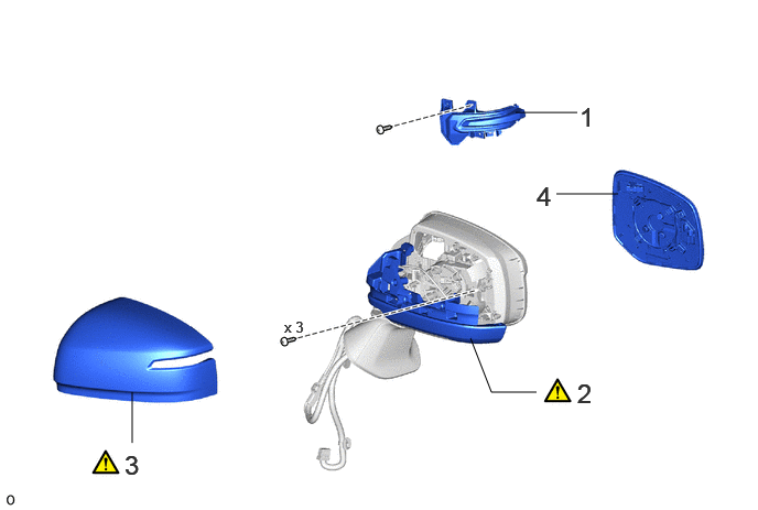
4.875,1.063 5.458,1.063 false 5.26,1.833 5.844,1.833 false 4.448,3.198 4.646,3.708 4.646,3.708 5.073,3.708 false 1.25,4.188 1.25,3.708 false 5.073,1.708 5.354,2.063 0.281,0.354 18 false 4 1.177,4.25 1.458,4.604 0.281,0.354 18 false 3 5.458,3.573 5.74,3.927 0.281,0.354 18 false 2 5.479,0.958 5.76,1.313 0.281,0.354 18 false 1 2.688,3.01 3.146,3.208 0.458,0.198 10 false x 3
| Procedure | Part Name Code |

|

|

|
|
|---|---|---|---|---|---|
| 1 | SIDE TURN SIGNAL LIGHT ASSEMBLY LH | 81740 | - | - | - |
| 2 | COVER BODY | - | ( ) |
- | - |
| 3 | OUTER MIRROR COVER LH | 87945 | () |
- | - |
| 4 | OUTER MIRROR LH | 87961 | - | - | - |
CAUTION / NOTICE / HINT
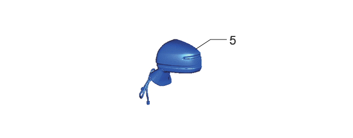
3.969,1 4.271,0.802 4.271,0.802 4.604,0.802 false 4.656,0.667 4.938,1.021 0.281,0.354 18 false 5
| Procedure | Part Name Code |
|
|
|
|
|---|---|---|---|---|---|
| 5 | OUTER REAR VIEW MIRROR ASSEMBLY LH | 87940 | - | - | - |
- HINT:
-
·
Use the same procedure for the RH and LH sides.
·The procedure described below is for the LH side.
PROCEDURE

 81740 1.INSTALL SIDE TURN SIGNAL LIGHT ASSEMBLY LH
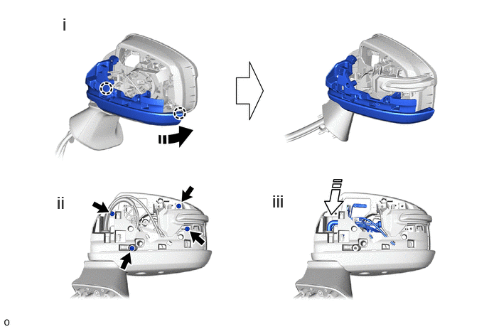
2.INSTALL COVER BODY
a.
0.833,2.823 1.115,3.177 0.281,0.354 18 false ii 0.917,0.208 1.198,0.563 0.281,0.354 18 false i 3.99,2.802 4.271,3.156 0.281,0.354 18 false iii

|
Install in this Direction | - | - |
i.
Push the cover body as shown in the illustration.
ii.
Install the 4 screws.
iii.
Push the harness sub-assembly and the television camera wire.
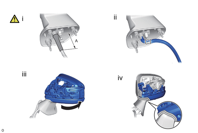
b.
0.792,0.521 1.073,0.875 0.281,0.354 18 false i 4.115,0.469 4.74,0.802 0.625,0.333 18 false ii 0.792,2.531 1.417,2.865 0.625,0.333 18 false iii 4.26,2.667 4.885,3 0.625,0.333 18 false iv 2.719,1.396 2.875,1.594 0.156,0.198 10 false A
|
|
Move in this Direction |

|
Vinyl Tape |

|
Protective Tape | - | - |
i.
Wind vinyl tape as shown in the illustration.
- Standard Measurement:
-
Area Measurement A 50 mm (1.97 in.)
ii.
Attach the wire harness clamp.
iii.
Move the outer rear view mirror assembly LH to the driving position.
iv.
Remove the protective tape.
87945 3.INSTALL OUTER MIRROR COVER LH
87961 4.INSTALL OUTER MIRROR LH
87940 5.INSTALL OUTER REAR VIEW MIRROR ASSEMBLY LH