EXTERIOR PANELS / TRIM FRONT BUMPER(for Standard) REMOVAL
CAUTION / NOTICE / HINT
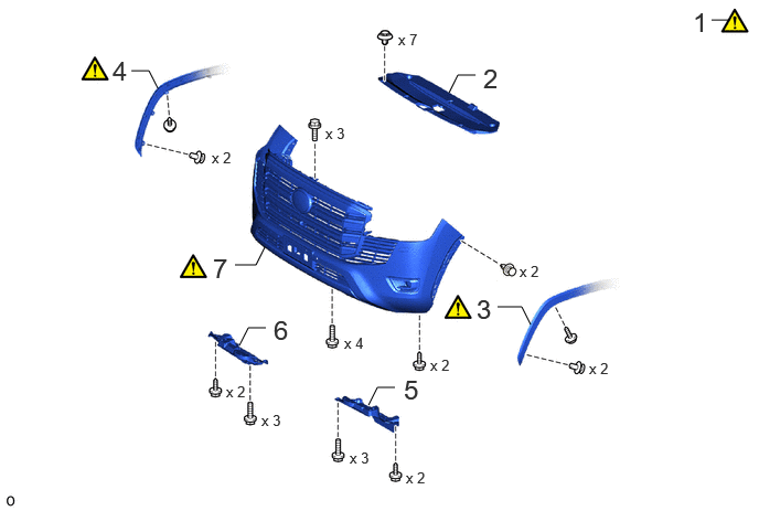
| Procedure | Part Name Code |

|

|

|
|
|---|---|---|---|---|---|
| 1 | PRECAUTION | - | ( ) |
- | - |
| 2 | UPPER RADIATOR SUPPORT SEAL | 53292A | - | - | - |
| 3 | FRONT FENDER MOULDING SUB-ASSEMBLY LH | 75602A | () |
- | - |
| 4 | FRONT FENDER MOULDING SUB-ASSEMBLY RH | 75601A | () |
- | - |
| 5 | ENGINE SIDE COVER SUB-ASSEMBLY LH | 51044 | - | - | - |
| 6 | ENGINE SIDE COVER SUB-ASSEMBLY RH | 51043 | - | - | - |
| 7 | FRONT BUMPER ASSEMBLY | - | () |
- | - |
CAUTION / NOTICE / HINT
The necessary procedures (adjustment, calibration, initialization or registration) that must be performed after parts are removed, installed or replaced during the front bumper assembly removal/installation are shown below.
| Replaced Part or Performed Procedures | Necessary Procedures | Effect/Inoperative Function when Necessary Procedures are not Performed | Link |
|---|---|---|---|
| Front bumper assembly (Including removal and installation) | Front television camera view adjustment | Panoramic view monitor system | () |
|
·
Front television camera assembly (Including removal and installation)
·
Radiator grille (Including removal and installation) |
Front television camera view adjustment | Panoramic view monitor system | () |
- HINT:
-
·
When the front bumper is damaged or deformed due to an accident or contact with other objects, etc., or the bumper installation area on the body is repaired, it is necessary to perform millimeter wave radar sensor adjustment.
-Target Adjustment (Triangle Target):
-Target Adjustment (Flat Surface Target):
-Driving Adjustment:
Click hereADAS / AD>ADVANCED DRIVER ASSISTANCE SYSTEM>MILLIMETER WAVE RADAR SENSOR>DRIVING ADJUSTMENT
·When the front bumper is damaged or deformed due to an accident or contact with other objects, etc., or the bumper installation area on the body is repaired, it is necessary to perform ultrasonic sensor detection angle measurement.
Click hereAudio / Visual / Telematics>PARK ASSIST / MONITORING>PARKING SUPPORT BRAKE SYSTEM>CALIBRATION
PROCEDURE

 1. PRECAUTION
|
|
|
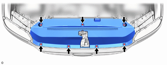
53292A 2.REMOVE UPPER RADIATOR SUPPORT SEAL
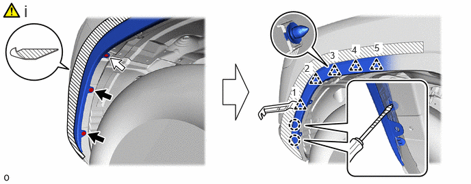
75602A 3.REMOVE FRONT FENDER MOULDING SUB-ASSEMBLY LH

|
Clip |

|
Screw |
Remove the front fender moulding sub-assembly LH.
1. Put protective tape around the front fender moulding sub-assembly LH.
2. Using a 4 mm hexagon socket wrench, remove the screw.
3. Remove the 2 clips.
4. Insert a screwdriver with its tip wrapped with protective tape into the gap and detach the claw.
5. Using moulding remover B, detach the clip in the order shown in the illustration and remove the front fender moulding sub-assembly LH as shown in the illustration.
- NOTICE:
-
Detach the clip one by one.
75601A 4.REMOVE FRONT FENDER MOULDING SUB-ASSEMBLY RH
Use the same procedure described for LH side.
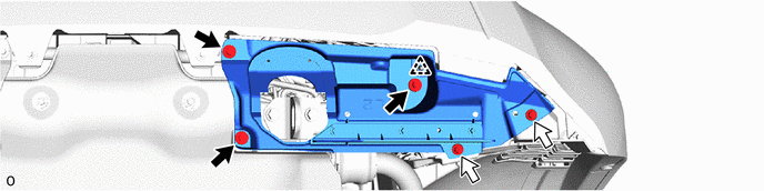
51044 5.REMOVE ENGINE SIDE COVER SUB-ASSEMBLY LH
|
|
Bolt |
|
Screw |
51043 6.REMOVE ENGINE SIDE COVER SUB-ASSEMBLY RH
Use the same procedure described for the LH side.
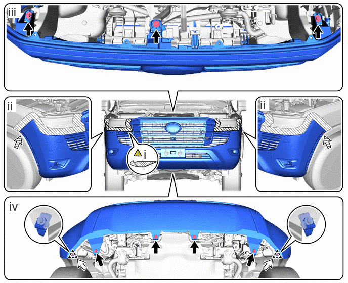
7.REMOVE FRONT BUMPER ASSEMBLY
|
|
Bolt |
|
Screw |

|
Clip | - | - |
Put protective tape around the front bumper assembly.
Remove the 2 clips.
Remove the 3 bolts.
Remove the 4 bolts and 2 screws and detach the clip.
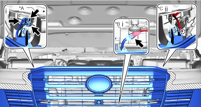
| *A | w/ Panoramic View Monitor System | *B | w/ Winch |
| *C | w/ Headlight Cleaner System | - | - |
|
|
Connector |
|
Headlight Cleaner Hose |
Disconnect each connector.
w/ Headlight Cleaner System:
1. Detach the claw and disconnect the headlight cleaner hose.

|
Place Hand Here |

|
Remove in this Direction (1) |

|
Remove in this Direction (2) | - | - |
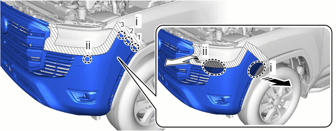
Place your hand at the position shown in the illustration and pull in the direction of the arrow to detach the claws in the order shown in the illustration.
Place your hand at the position shown in the illustration and lift up in the direction of the arrow to detach the claw.
Use the same procedure for the other side.
|
|
Remove in this Direction | - | - |
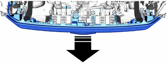
Detach the guide and claw and remove the front bumper assembly as shown in the illustration.