JF2BM TRANSFER / 4WD / AWD TRANSFER SYSTEM Rear Differential Lock Switch Circuit
WIRING DIAGRAM
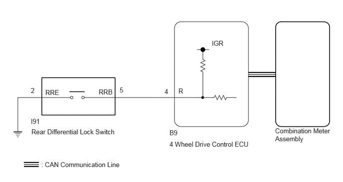
PROCEDURE
Turn the ignition switch to ON.
Press the rear differential lock switch.
Check the rear differential lock indicator light.
- Result:
-
Result Proceed to Blinking: Blinks at 0.5 second intervals (0.5 seconds on and 0.5 seconds off)
Rear differential lock indicator light blinks or illuminates A Rear differential lock indicator light remains off regardless of switch operation B Rear differential lock indicator light remains illuminated regardless of switch operation C
Turn the ignition switch off.
A
B
C
Select "Bus Check" from the System Selection Menu screen, and follow the prompts on the screen to inspect the CAN bus.
- CAN Bus Check
- 50007
- OK:
-
"Bus Check" indicates no malfunctions in CAN communication.
- Result:
-
Proceed to OK NG
OK
NG
Click herePower Source / Network>NETWORKING>CAN COMMUNICATION SYSTEM>HOW TO PROCEED WITH TROUBLESHOOTING
Turn the ignition switch to ON.
According to the display on the GTS, read the Data List.
- Powertrain > Four Wheel Drive > Data List
-
Tester Display Rear Differential Lock Control Switch - 50003 442 19
- Powertrain > Four Wheel Drive > Data List
-
Tester Display Measurement Item Range Normal Condition Diagnostic Note Rear Differential Lock Control Switch Rear differential lock switch status OFF or ON OFF: Not pressed
ON: Pressed and held-
- OK:
-
OK: Display changes according to rear differential lock switch operation
Turn the ignition switch off.
- Result:
-
Proceed to OK NG
OK
NG
Using the GTS, perform the Active Test "Rear DIFF LOCK Indicator" of the combination meter assembly.
- Body Electrical > Combination Meter > Active Test
-
Tester Display Rear DIFF LOCK Indicator - 50004 409 99
- OK:
-
The rear differential lock indicator light illuminates or turns off in accordance with the operation
- Result:
-
Proceed to OK NG
OK
for LHD: Click hereDrivetrain>JF2BM (TRANSFER / 4WD / AWD)>4WD CONTROL ECU (for LHD)>REMOVAL
for RHD: Click hereDrivetrain>JF2BM (TRANSFER / 4WD / AWD)>4WD CONTROL ECU (for RHD)>REMOVAL
NG
Click hereVehicle Interior>METER / GAUGE / DISPLAY>METER / GAUGE SYSTEM>HOW TO PROCEED WITH TROUBLESHOOTING
Inspect the rear differential lock switch.
Click hereDrivetrain>AXLE AND DIFFERENTIAL>REAR DIFFERENTIAL LOCK CONTROL SWITCH>INSPECTION
- Result:
-
Proceed to OK NG
OK
NG
Disconnect the B9 4 wheel drive control ECU connector.
Disconnect the I91 Rear differential lock switch connector.
Measure the resistance according to the value(s) in the table below.
- Standard Resistance:
-
Tester Connection Condition Specified Condition Click Location & Routing(B9,I91)Location & Routingewd_type=routing;type=c,c;code=B9,I91
Click Connector(B9)Instrument Panel>Engine Room Main Wire / Heater Blower Wire>4 Wheel Drive Control ECUewd_type=component;type=c;code=B9;pinno=4
B9-4 (R) - I91-5 (RRB) Always Below 1 Ω I91-2 (RRE) - Body ground Always Below 1 Ω B9-4 (R) or I91-5 (RRB) - Body ground Always 10 kΩ or higher
Connect the I91 Rear differential lock switch connector.
Connect the B9 4 wheel drive control ECU connector.
- Result:
-
Proceed to OK NG
OK
for LHD: Click hereDrivetrain>JF2BM (TRANSFER / 4WD / AWD)>4WD CONTROL ECU (for LHD)>REMOVAL
for RHD: Click hereDrivetrain>JF2BM (TRANSFER / 4WD / AWD)>4WD CONTROL ECU (for RHD)>REMOVAL
NG
Select "Bus Check" from the System Selection Menu screen, and follow the prompts on the screen to inspect the CAN bus.
- CAN Bus Check
- 50007
- OK:
-
"Bus Check" indicates no malfunctions in CAN communication.
- Result:
-
Proceed to OK NG
OK
NG
Click herePower Source / Network>NETWORKING>CAN COMMUNICATION SYSTEM>HOW TO PROCEED WITH TROUBLESHOOTING
Turn the ignition switch to ON.
According to the display on the GTS, read the Data List.
- Powertrain > Four Wheel Drive > Data List
-
Tester Display Rear Differential Lock Indicator Request - 50003 442 41
Turn the rear differential lock switch on and off several times and check the GTS display condition of the rear differential lock indicator light.
- Powertrain > Four Wheel Drive > Data List
-
Tester Display Measurement Item Range Normal Condition Diagnostic Note Rear Differential Lock Indicator Request Rear differential lock indicator light request OFF, ON, Blink1, Blink2 or Blink3 OFF: Indicator light turns off
ON: Indicator light illuminates
Blink1: Indicator light blinks
Blink2: Indicator light blinks 3 times
Blink3: Indicator light rapidly blinks·Blinking: 0.5 second intervals (0.5 seconds on and 0.5 seconds off)
·Rapidly blinking: 0.25 second intervals (0.25 seconds on and 0.25 seconds off)
- Result:
-
Result Proceed to Data List continues to display ON even when differential lock switch is operated A Data List display changes according to differential lock switch operation B
Turn the ignition switch off.
A
for LHD: Click hereDrivetrain>JF2BM (TRANSFER / 4WD / AWD)>4WD CONTROL ECU (for LHD)>REMOVAL
for RHD: Click hereDrivetrain>JF2BM (TRANSFER / 4WD / AWD)>4WD CONTROL ECU (for RHD)>REMOVAL
B
Click hereVehicle Interior>METER / GAUGE / DISPLAY>METER / GAUGE SYSTEM>HOW TO PROCEED WITH TROUBLESHOOTING