THEFT DETERRENT / KEYLESS ENTRY THEFT DETERRENT SYSTEM Tilt Sensor Circuit
DESCRIPTION
The main body ECU (multiplex network body ECU) operates the tilt sensor (theft warning ultrasonic and tilt sensor) via the LIN communication line. The tilt sensor (theft warning ultrasonic and tilt sensor) sends information regarding changes in the vehicle tilt angle to the main body ECU (multiplex network body ECU). The main body ECU (multiplex network body ECU) checks whether the vehicle body is being tilted without authorization.
- HINT:
-
In the following situations, the tilt sensor (theft warning ultrasonic and tilt sensor) may operate and cause the theft deterrent system to operate even when the sensor is normal.
-
·
The vehicle is transported by a ferry, trailer or train.
·The vehicle is parked in a multi-story parking facility.
·The vehicle is washed by an automatic car wash.
·A tire blows out.
·The vehicle is jacked up for a tire or wheel change.
·An earthquake occurs or the road subsides.
·Goods such as skis or snowboards are loaded or unloaded.
WIRING DIAGRAM
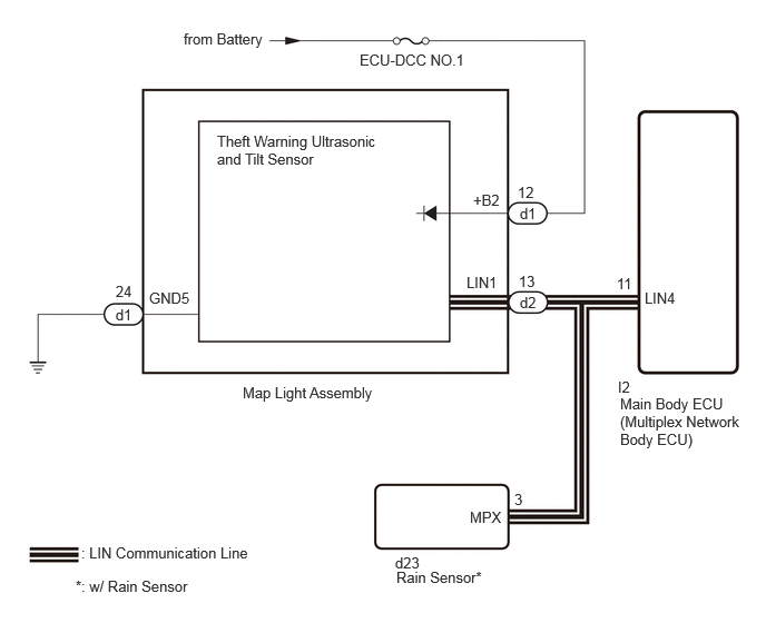
CAUTION / NOTICE / HINT
- NOTICE:
-
·
Inspect the fuses for circuits related to this system before performing the following procedure.
·If the main body ECU (multiplex network body ECU) is replaced, refer to the Service Bulletin.
PROCEDURE
According to the display on the GTS, read the Data List.
- Body Electrical > Main Body > Data List
-
Tester Display Measurement Item Range Normal Condition Communication Intrusion Sensor 1 Theft warning ultrasonic and tilt sensor connecting ON or OFF ON: Theft warning ultrasonic and tilt sensor connected
OFF: Theft warning ultrasonic and tilt sensor not connected
- Body Electrical > Main Body > Data List
-
Tester Display Communication Intrusion Sensor 1 - 50003 449 1655
- OK:
-
"ON" appears on GTS screen.
- Result:
-
Proceed to OK NG
OK
Click hereVehicle Interior>THEFT DETERRENT / KEYLESS ENTRY>THEFT DETERRENT SYSTEM>PROBLEM SYMPTOMS TABLE
NG
Disconnect the I2 main body ECU (multiplex network body ECU) connector.
Disconnect the d2 map light assembly connector.
Disconnect the d23 rain sensor connector.*
*: w/ Rain Sensor
Measure the resistance according to the value(s) in the table below.
- Standard Resistance:
-
Tester Connection Condition Specified Condition Click Location & Routing(I2,d2)Location & Routingewd_type=routing;type=c,c;code=I2,d2
Click Connector(d2)Body>No. 1 Roof Wire>Map Light Assembly (Front)ewd_type=component;type=c;code=d2;pinno=13
I2-11 (LIN4) - d2-13 (LIN1) Always Below 1 Ω I2-11 (LIN4) or d2-13 (LIN1) - Other terminals and body ground Always 10 kΩ or higher
- Result:
-
Proceed to OK NG
OK
NG
Remove the map light assembly.
Click hereVehicle Interior>LIGHTING (INT)>PERSONAL LIGHT>REMOVAL
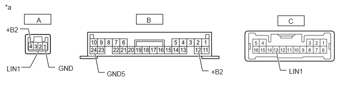
| *a | Component with harness connected (Map Light Assembly) |
- | - |
Measure the resistance according to the value(s) in the table below.
- Standard Resistance:
-
Tester Connection Condition Specified Condition A-1 (GND) - B-24 (GND) Always Below 1 Ω A-2 (LIN1) - C-13 (LIN1) Always Below 1 Ω A-4 (+B2) - B-12 (+B2) Always Below 1 Ω
- Result:
-
Proceed to OK NG
OK
NG
Replace the intrusion sensor (Theft warning ultrasonic and tilt sensor).
Click hereVehicle Interior>THEFT DETERRENT / KEYLESS ENTRY>INTRUSION SENSOR>REMOVAL
According to the display on the GTS, read the Data List.
- Body Electrical > Main Body > Data List
-
Tester Display Measurement Item Range Normal Condition Communication Intrusion Sensor 1 Theft warning ultrasonic and tilt sensor connecting ON or OFF ON: Theft warning ultrasonic and tilt sensor connected
OFF: Theft warning ultrasonic and tilt sensor not connected
- Body Electrical > Main Body > Data List
-
Tester Display Communication Intrusion Sensor 1 - 50003 449 1655
- OK:
-
"ON" appears on GTS screen.
- Result:
-
Proceed to OK NG
OK
Click hereVehicle Interior>THEFT DETERRENT / KEYLESS ENTRY>THEFT DETERRENT SYSTEM>PROBLEM SYMPTOMS TABLE
NG
for LHD: Click herePower Source / Network>POWER DISTRIBUTION>MAIN BODY ECU (for LHD)>REMOVAL
for RHD: Click herePower Source / Network>POWER DISTRIBUTION>MAIN BODY ECU (for RHD)>REMOVAL