AC60F AUTOMATIC TRANSMISSION / TRANSAXLE SHIFT LEVER INSTALLATION
CAUTION / NOTICE / HINT
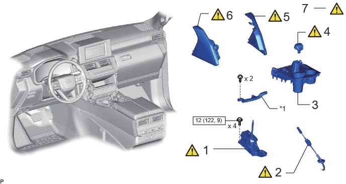
| Procedure | Part Name Code |

|

|

|
|
|---|---|---|---|---|---|
| 1 | FLOOR SHIFT LEVER ASSEMBLY | - | ( ) |
- | - |
| 2 | TRANSMISSION CONTROL CABLE ASSEMBLY | 33820B | () |
- | - |
| 3 | UPPER CONSOLE PANEL ASSEMBLY | - | - | - | - |
| 4 | SHIFT LEVER KNOB SUB-ASSEMBLY | 33504F | () |
- | - |
| 5 | LOWER NO. 2 INSTRUMENT PANEL PAD SUB-ASSEMBLY | 55403H | () |
- | - |
| 6 | INTEGRATION CONTROL AND PANEL SUB-ASSEMBLY | 84012 | () |
- | - |
| 7 | INSPECT SHIFT LEVER POSITION | - | () |
- | - |
| *1 | NO. 2 CONSOLE BOX RETAINER | - | - |

|
N*m (kgf*cm, ft.*lbf): Specified torque | - | - |
PROCEDURE

 1.INSTALL FLOOR SHIFT LEVER ASSEMBLY
|
|
|


|
Bolt A |

|
Bolt B |

|
Bolt C |

|
Bolt D |
Install the floor shift lever assembly to the vehicle body with the 4 bolts.
- Torque:
- 12 N*m (122 kgf*cm, 9 ft.*lbf)
- HINT:
-
Tightening order: Temporarily install bolt A, bolt B, bolt C and bolt D → Tighten bolt A → Tighten bolt B → Tighten bolt C → Tighten bolt D
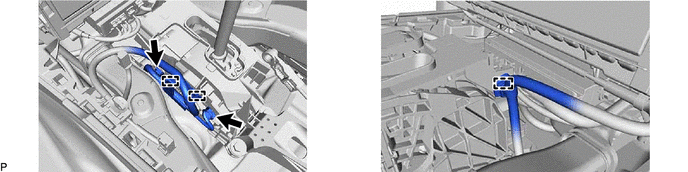
33820B 2.CONNECT TRANSMISSION CONTROL CABLE ASSEMBLY
|
|
|
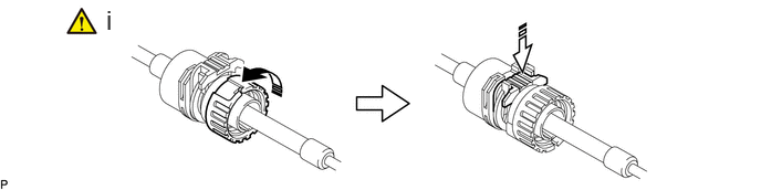

|
Rotate approximately 180° |

|
Push In |
Rotate the nut of the transmission control cable assembly approximately 180° in the direction shown in the illustration, and while holding the nut in that position, push in the lock.
- NOTICE:
-
Rotating the nut too much will damage the internal spring, and the transmission control cable assembly will not be reusable. Do not turn the nut too far.
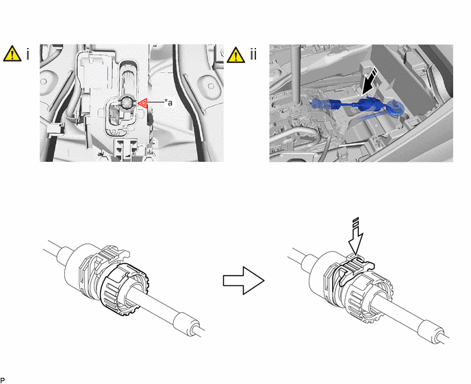
| *a | N Position Mark | - | - |
|
|
Install in this Direction |
|
Push In |
The shift lever shaft position matches N position mark on the lower position indicator housing.
Connect the transmission control cable assembly to the floor shift lever assembly.
- NOTICE:
-
·
Connect the transmission control cable assembly with the stopper upwards.
·Make sure that the transmission control cable assembly is securely locked.
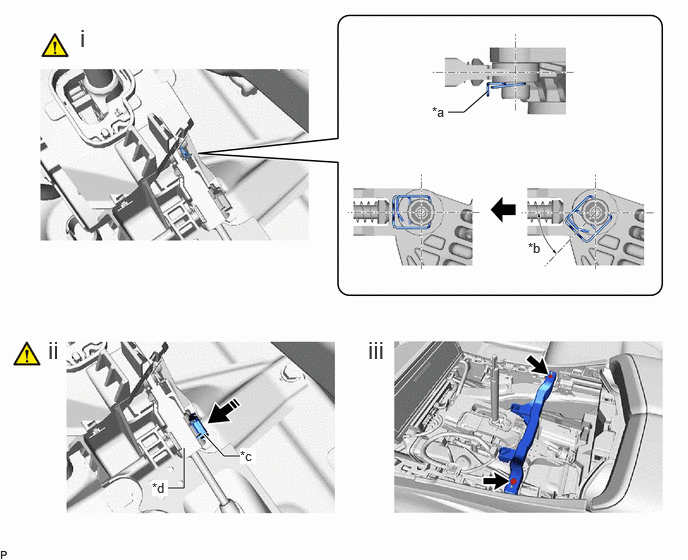
| *a | Clip | *b | 45° to 60° |
| *c | Lock Piece | *d | Adjuster Case |
|
|
Push It | - | - |
While engaging the clip as shown in the illustration, connect the transmission control cable assembly to the floor shift lever assembly.
- NOTICE:
-
·
Check that the lock piece is pulled out.
·Push the end of the transmission control cable assembly all the way to the base of the transmission floor shift assembly pin.
·Connect the transmission control cable assembly so that the lock piece faces the passenger side.
Push the lock piece into the adjuster case.
- NOTICE:
-
·
Check that the shift lever is in N.
·Securely push in the lock piece until it is engaged.
·Make sure that lever shaft position is not moved in shift direction during adjuster locking operation.
-Do not touch the lever shaft and knob during locking operation.
-Do not pull or push the adjuster case in shift direction during locking operation.
Install the No. 2 console box retainer to the rear console box sub-assembly with the 2 screws.
3.INSTALL UPPER CONSOLE PANEL ASSEMBLY
33504F 4.INSTALL SHIFT LEVER KNOB SUB-ASSEMBLY
|
|
Click here() |
55403H 5.INSTALL LOWER NO. 2 INSTRUMENT PANEL PAD SUB-ASSEMBLY
|
|
Click here() |
84012 6.INSTALL INTEGRATION CONTROL AND PANEL SUB-ASSEMBLY
|
|
Click here() |
7.INSPECT SHIFT LEVER POSITION
|
|
Click here() |