LIGHTING (EXT) LIGHTING SYSTEM(w/ Headlight ECU) B241A1C Rear Height Sensor Circuit Voltage Out of Range
DESCRIPTION
The headlight ECU sub-assembly LH determines the vehicle height and performs automatic headlight beam level control based on signals from the rear height control sensor sub-assembly LH via direct line.
| DTC No. | Detection Item | DTC Detection Condition | Trouble Area | DTC Output from | Priority |
|---|---|---|---|---|---|
| B241A1C | Rear Height Sensor Circuit Voltage Out of Range |
Detection condition:
The ignition switch is ON.
Malfunction status:
Abnormal vehicle height continuously detected
Malfunction duration:
10 seconds or more |
·
Rear height control sensor sub-assembly LH
·
Harness or connector
·
Headlight ECU sub-assembly LH |
Headlight Control | A |
WIRING DIAGRAM
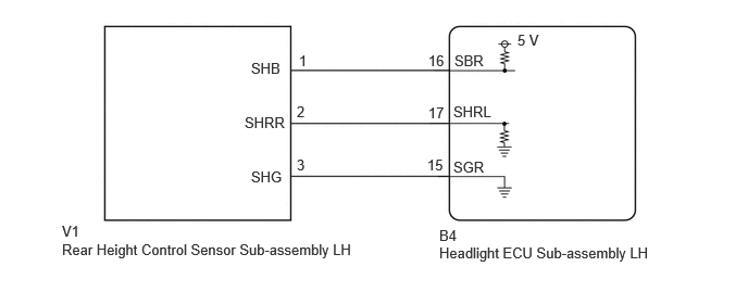
CAUTION / NOTICE / HINT
- NOTICE:
-
·
If the headlight ECU sub-assembly LH has been replaced, it is necessary to synchronize the vehicle information and initialize the headlight ECU sub-assembly LH.
Click hereVehicle Exterior>LIGHTING (EXT)>LIGHTING SYSTEM (w/ Headlight ECU)>REGISTRATION
·If any of the following are performed, it is necessary to initialize the headlight ECU sub-assembly LH.
Click hereVehicle Exterior>LIGHTING (EXT)>LIGHTING SYSTEM (w/ Headlight ECU)>REGISTRATION
-Replacement of the rear height control sensor sub-assembly LH
-Removal/installation of the rear height control sensor sub-assembly LH
-Work that changes the vehicle height such as replacement of suspension components
·When replacing the headlight ECU sub-assembly LH, always replace it with a new one. If a headlight ECU sub-assembly LH which was installed to another vehicle is used, the information stored in it will not match the information from the vehicle and a DTC may be stored.
PROCEDURE
Clear the DTCs.
- Body Electrical > Headlight Control > Clear DTCs
- 50002 462
- Result:
-
Proceed to NEXT
NEXT
Pre-procedure1
Turn ignition switch to ON.
Wait 10 seconds or more.
Post-procedure1
Check for DTCs.
- Body Electrical > Headlight Control > Trouble Codes
- 50001 462
- Result:
-
Result Proceed to B241A1C is not output A B241A1C is output B
Procedure1
None
A
Click hereGeneral>INTRODUCTION>HOW TO TROUBLESHOOT ECU CONTROLLED SYSTEMS>HOW TO PROCEED WITH TROUBLESHOOTING
B
OK
NG
Pre-procedure1
Disconnect the B4 headlight ECU sub-assembly LH connector.
Procedure1
Measure the resistance according to the value(s) in the table below.
- Standard Resistance:
-
Tester Connection Condition Specified Condition Click Location & Routing(V1,B4)Location & Routingewd_type=routing;type=c,c;code=V1,B4
Click Connector(V1)Body>Differential Wire / Frame Wire>Height Control Sensor Sub-Assembly Rear RHewd_type=component;type=c;code=V1;pinno=1,2,3
V1-1 (SHB) - B4-16 (SBR) Always Below 1 Ω V1-2 (SHRR) - B4-17 (SHRL) Always Below 1 Ω V1-3 (SHG) - B4-15 (SGR) Always Below 1 Ω V1-1 (SHB) or B4-16 (SBR) - Body ground Always 10 kΩ or higher V1-2 (SHRR) or B4-17 (SHRL) - Body ground Always 10 kΩ or higher
- Result:
-
Proceed to OK NG
Post-procedure1
None
OK
NG