LIGHTING (EXT) LIGHTING SYSTEM(w/ Headlight ECU) Hazard Warning Switch Circuit
DESCRIPTION
The combination meter assembly receives the hazard warning signal switch assembly ON signal and controls the operation of the hazard warning lights.
WIRING DIAGRAM
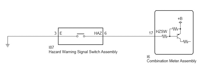
CAUTION / NOTICE / HINT
- NOTICE:
-
·
When replacing the combination meter assembly, always replace it with a new one. If a combination meter assembly which was installed to another vehicle is used, the information stored in it will not match the information from the vehicle and a DTC may be stored.
·When replacing the combination meter assembly, update the ECU security key.
Click hereGeneral>SETUP>WHEN REPLACING OR REMOVING/INSTALLING PARTS>UPDATE ECU SECURITY KEY
PROCEDURE
Read the Data List according to the display on the GTS.
- Body Electrical > Combination Meter > Data List
-
Tester Display Measurement Item Range Normal Condition Diagnostic Note Hazard Flasher Switch Hazard warning signal switch signal OFF or ON OFF: Hazard warning signal switch off
ON: Hazard warning signal switch on-
- Body Electrical > Combination Meter > Data List
-
Tester Display Hazard Flasher Switch - 50003 409 39
- OK:
-
Normal conditions listed above are displayed.
- Result:
-
Proceed to OK NG
OK
NG
OK
NG
Disconnect the I6 combination meter assembly connector.
Measure the resistance according to the value(s) in the table below.
- Standard Resistance:
-
Tester Connection Condition Specified Condition Click Location & Routing(I87,I6)Location & Routingewd_type=routing;type=c,c;code=I87,I6
I87-6 (HAZ) - I6-17 (HZSW) Always Below 1 Ω I87-6 (HAZ) or I6-17 (HZSW) - Body ground Always 10 kΩ or higher I87-3 (E) - Body ground Always Below 1 Ω
- Result:
-
Proceed to OK NG
OK
NG