Home › Engine / Hybrid System › 1GR-FE (ENGINE CONTROL) › SFI SYSTEM
RM38G0E _51 Engine / Hybrid System _100527 1GR-FE ENGINE CONTROL _0469186 SFI SYSTEM J

1GR-FE ENGINE CONTROL  SFI SYSTEM  ECM Power Source Circuit  


DESCRIPTION

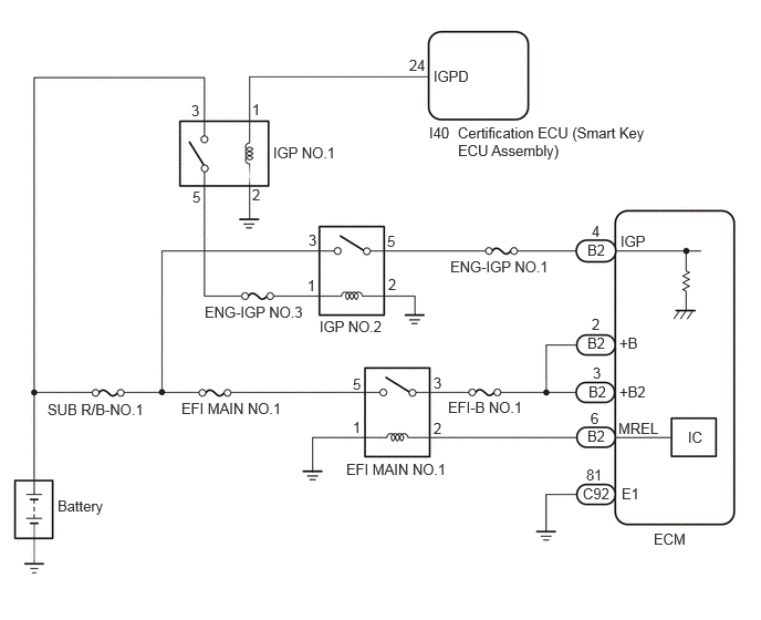
When the ignition switch is turned to ON, battery voltage is applied to the IGP terminal of the ECM. The output signal from the MREL terminal of the ECM causes current to flow to the coil of the EFI-MAIN NO.1 relay, closing the contact of the EFI-MAIN NO.1 relay and supplying power to terminals +B and +B2 of the ECM.

WIRING DIAGRAM
A488685E01
0.542,4.677 1.104,4.906 0.563,0.229 10 false Battery 0.448,3.771 1.469,3.979 1.021,0.208 10 false SUB R/B-NO.1 1.708,3.76 2.708,3.927 1,0.167 10 false EFI MAIN NO.1 2.573,1.354 3.24,1.552 0.667,0.198 10 false IGP NO.1 4.313,1.167 6.198,1.615 1.885,0.448 10 false Certification ECU (Smart Key ECU Assembly) 4.24,2.427 5.271,2.635 1.031,0.208 10 false ENG-IGP NO.1 4.219,3.75 5.031,3.958 0.813,0.208 10 false EFI-B NO.1 6.156,4.99 6.563,5.24 0.406,0.25 10 false ECM 3.26,4.333 4.26,4.5 1,0.167 10 false EFI MAIN NO.1 1.802,0.958 1.958,1.146 0.156,0.188 10 false 3 2.375,1.75 2.531,1.938 0.156,0.188 10 false 2 2.375,0.948 2.531,1.135 0.156,0.188 10 false 1 3.854,0.531 4.052,0.719 0.198,0.188 10 false 24 4.042,1.167 4.271,1.375 0.229,0.208 10 false I40 3.323,3.531 3.479,3.719 0.156,0.188 10 false 5 1.813,1.771 1.969,1.958 0.156,0.188 10 false 5 4.083,3.521 4.24,3.708 0.156,0.188 10 false 3 3.323,3.938 3.479,4.125 0.156,0.188 10 false 1 4.083,3.948 4.24,4.135 0.156,0.188 10 false 2 5.531,2.271 5.792,2.49 0.26,0.219 10 false B2 5.531,3.146 5.792,3.365 0.26,0.219 10 false B2 5.542,3.604 5.802,3.823 0.26,0.219 10 false B2 5.531,4.021 5.792,4.24 0.26,0.219 10 false B2 5.49,4.563 5.781,4.771 0.292,0.208 10 false C92 5.573,2.094 5.729,2.281 0.156,0.188 10 false 4 5.573,2.969 5.729,3.156 0.156,0.188 10 false 2 5.583,3.427 5.74,3.615 0.156,0.188 10 false 3 5.563,3.854 5.719,4.042 0.156,0.188 10 false 6 5.521,4.385 5.719,4.573 0.198,0.188 10 false 81 5.844,2.188 6.135,2.396 0.292,0.208 10 false IGP 5.833,3.146 6.125,3.354 0.292,0.208 10 false +B 5.833,3.604 6.125,3.813 0.292,0.208 10 false +B2 5.823,3.948 6.313,4.198 0.49,0.25 10 false MREL 5.854,4.563 6.146,4.771 0.292,0.208 10 false E1 4.083,0.635 4.573,0.885 0.49,0.25 10 false IGPD 6.479,4.031 6.771,4.24 0.292,0.208 10 false IC 1.927,2.854 2.958,3.063 1.031,0.208 10 false ENG-IGP NO.3 3.01,2.99 3.677,3.188 0.667,0.198 10 false IGP NO.2 3.656,2.594 3.813,2.781 0.156,0.188 10 false 2 2.896,2.604 3.052,2.792 0.156,0.188 10 false 1 2.906,2.177 3.063,2.365 0.156,0.188 10 false 3 3.646,2.188 3.802,2.375 0.156,0.188 10 false 5

CAUTION / NOTICE / HINT

NOTICE:
·

Inspect the fuses for circuits related to this system before performing the following procedure.

·

After the ignition switch is turned off, there may be a waiting time before disconnecting the negative (-) battery terminal.

Click hereGeneral>SETUP>WHEN DISCONNECTING OR RECONNECTING BATTERY TERMINAL>BEFORE DISCONNECTING BATTERY

·

When disconnecting and reconnecting the battery.

Click hereGeneral>SETUP>WHEN DISCONNECTING OR RECONNECTING BATTERY TERMINAL>WORK PROCEDURE

HINT:

When disconnecting and reconnecting the battery, there is an automatic learning function that completes learning when the respective system is used.

Click hereGeneral>SETUP>WHEN DISCONNECTING OR RECONNECTING BATTERY TERMINAL>AUTOMATIC LEARNING CHART


PROCEDURE

1.CHECK TERMINAL VOLTAGE (IGP VOLTAGE)
a.

Disconnect the ECM connector.


b.

Turn the ignition switch to ON.


c.

Measure the voltage according to the value(s) in the table below.

Standard Voltage:
Tester Connection Condition Specified Condition

Click Location & Routing(B2)Location & Routing

Click Connector(B2)Engine Compartment>Engine Room Main Wire / Lamp Wire / No. 2 Engine Room Wire / No. 2 Lamp Wire / No. 3 Engine Room Wire / No. 6 Engine Room Wire / Washer Wiring Assembly>ECM

B2-4 (IGP) - Body ground Ignition switch ON 11 to 14 V


Result:
Proceed to
OK
NG


OK

2.CHECK HARNESS AND CONNECTOR (ECM - BODY GROUND)

NG

7.INSPECT RELAY (IGP NO.2)
2.CHECK HARNESS AND CONNECTOR (ECM - BODY GROUND)
a.

Disconnect the ECM connector.


b.

Measure the resistance according to the value(s) in the table below.

Standard Resistance:
Tester Connection Condition Specified Condition

Click Location & Routing(C92)Location & Routing

Click Connector(C92)Engine Compartment>Connecting Wire / Cooling Fan Wire / Engine Wire / Fuel Pump Motor Wire / No. 1 Connecting Wire / No. 10 Engine Wire / No. 2 Connecting Wire / No. 3 Connecting Wire / No. 4 Connecting Wire / Sensor Wire / Turbocharger Wire>ECM

C92-81 (E1) - Body ground Always Below 1 Ω


Result:
Proceed to
OK
NG


OK

3.INSPECT RELAY (EFI MAIN NO.1)

NG

REPAIR OR REPLACE HARNESS OR CONNECTOR

3.INSPECT RELAY (EFI MAIN NO.1)
a.

Result:
Proceed to
OK
NG


OK

4.CHECK HARNESS AND CONNECTOR (RELAY (EFI MAIN NO.1) - BODY GROUND)

NG

REPLACE RELAY (EFI MAIN NO.1)

4.CHECK HARNESS AND CONNECTOR (RELAY (EFI MAIN NO.1) - BODY GROUND)
a.

Remove the relay (EFI MAIN NO.1).


b.

Measure the resistance according to the value(s) in the table below.

Standard Resistance:
Tester Connection Condition Specified Condition
1 (EFI MAIN NO.1 relay) - Body ground Always Below 1 Ω


Result:
Proceed to
OK
NG


OK

5.CHECK HARNESS AND CONNECTOR (RELAY (EFI MAIN NO.1) - ECM)

NG

REPAIR OR REPLACE HARNESS OR CONNECTOR

5.CHECK HARNESS AND CONNECTOR (RELAY (EFI MAIN NO.1) - ECM)
a.

Remove the relay (EFI MAIN NO.1).


b.

Disconnect the ECM connector.


c.

Measure the resistance according to the value(s) in the table below.

Standard Resistance:
Tester Connection Condition Specified Condition

Click Location & Routing(B2)Location & Routing

Click Connector(B2)Engine Compartment>Engine Room Main Wire / Lamp Wire / No. 2 Engine Room Wire / No. 2 Lamp Wire / No. 3 Engine Room Wire / No. 6 Engine Room Wire / Washer Wiring Assembly>ECM

2 (EFI MAIN NO.1 relay) - B2-6 (MREL) Always Below 1 Ω
2 (EFI MAIN NO.1 relay) or B2-6 (MREL) - Body ground and other terminals Always 10 kΩ or higher


Result:
Proceed to
OK
NG


OK

6.INSPECT TERMINAL VOLTAGE (POWER SOURCE OF EFI MAIN NO.1 RELAY)

NG

REPAIR OR REPLACE HARNESS OR CONNECTOR

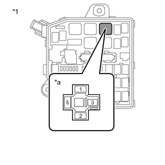
6.INSPECT TERMINAL VOLTAGE (POWER SOURCE OF EFI MAIN NO.1 RELAY)
A488865C01
1.135,1.625 1.448,1.823 0.313,0.198 10 false *a 0.26,0.156 0.573,0.354 0.313,0.198 10 false *1
*1 Engine Room Relay Block No. 2
*a EFI MAIN NO.1 Relay Terminal


a.

Remove the relay (EFI MAIN NO.1).


b.

Measure the voltage according to the value(s) in the table below.

Standard Voltage:
Tester Connection Condition Specified Condition
5 (EFI MAIN NO.1 relay) - Body ground Always 11 to 14 V


Result:
Proceed to
OK
NG


OK

REPAIR OR REPLACE HARNESS OR CONNECTOR (RELAY (EFI MAIN NO.1) - ECM)

NG

REPAIR OR REPLACE HARNESS OR CONNECTOR (RELAY (EFI MAIN NO.1) - BATTERY)

7.INSPECT RELAY (IGP NO.2)

Result:
Proceed to
OK
NG


OK

8.CHECK HARNESS AND CONNECTOR (RELAY (IGP NO.2) - ECM)

NG

REPLACE RELAY (IGP NO.2)

8.CHECK HARNESS AND CONNECTOR (RELAY (IGP NO.2) - ECM)
a.

Remove the relay (IGP NO.2).


b.

Disconnect the ECM connector.


c.

Measure the resistance according to the value(s) in the table below.

Standard Resistance:
Tester Connection Condition Specified Condition

Click Location & Routing(B2)Location & Routing

Click Connector(B2)Engine Compartment>Engine Room Main Wire / Lamp Wire / No. 2 Engine Room Wire / No. 2 Lamp Wire / No. 3 Engine Room Wire / No. 6 Engine Room Wire / Washer Wiring Assembly>ECM

5 (IGP NO.2 relay) - B2-4 (IGP) Always Below 1 Ω
5 (IGP NO.2 relay) or B2-4 (IGP) - Body ground and other terminals Always 10 kΩ or higher


Result:
Proceed to
OK
NG


OK

9.INSPECT TERMINAL VOLTAGE (POWER SOURCE OF IGP NO.2 RELAY)

NG

REPAIR OR REPLACE HARNESS OR CONNECTOR

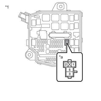
9.INSPECT TERMINAL VOLTAGE (POWER SOURCE OF IGP NO.2 RELAY)
A488866C01
0.177,0.156 0.49,0.354 0.313,0.198 10 false *1 2.01,1.854 2.323,2.052 0.313,0.198 10 false *a
*1 Engine Room Relay Block No. 2
*a IGP NO.2 Relay terminal


a.

Remove the relay (IGP NO.2).


b.

Measure the voltage according to the value(s) in the table below.

Standard Voltage:
Tester Connection Condition Specified Condition
3 (IGP NO.2 relay) - Body ground Always 11 to 14 V


Result:
Proceed to
OK
NG


OK

10.CHECK HARNESS AND CONNECTOR (RELAY (IGP NO.2) - BODY GROUND)

NG

REPAIR OR REPLACE HARNESS OR CONNECTOR (RELAY (IGP NO.2) - BATTERY)

10.CHECK HARNESS AND CONNECTOR (RELAY (IGP NO.2) - BODY GROUND)
a.

Remove the relay (IGP NO.2).


b.

Measure the resistance according to the value(s) in the table below.

Standard Resistance:
Tester Connection Condition Specified Condition
2 (IGP NO.2 relay) - Body ground Always Below 1 Ω


Result:
Proceed to
OK
NG


OK

11.INSPECT RELAY (IGP NO.1)

NG

REPAIR OR REPLACE HARNESS OR CONNECTOR

11.INSPECT RELAY (IGP NO.1)

Result:
Proceed to
OK
NG


OK

12.INSPECT TERMINAL VOLTAGE (POWER SOURCE OF IGP NO.1 RELAY)

NG

REPLACE RELAY (IGP NO.1)

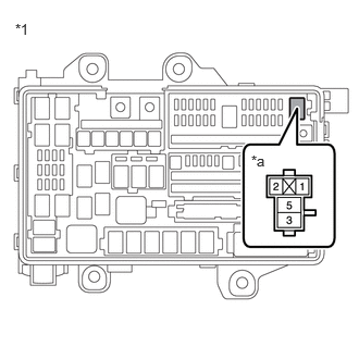
12.INSPECT TERMINAL VOLTAGE (POWER SOURCE OF IGP NO.1 RELAY)
A488867C01
0.146,0.198 0.458,0.396 0.313,0.198 10 false *1 2.406,1.458 2.719,1.656 0.313,0.198 10 false *a
*1 Engine Room Relay Block No. 1
*a IGP NO.1 Relay terminal


a.

Remove the relay (IGP NO.1).


b.

Measure the voltage according to the value(s) in the table below.

Standard Voltage:
Tester Connection Condition Specified Condition
3 (IGP NO.1 relay) - Body ground Always 11 to 14 V


Result:
Proceed to
OK
NG


OK

13.CHECK HARNESS AND CONNECTOR (RELAY (IGP NO.1) - BODY GROUND)

NG

REPAIR OR REPLACE HARNESS OR CONNECTOR (RELAY (IGP NO.1) - BATTERY)

13.CHECK HARNESS AND CONNECTOR (RELAY (IGP NO.1) - BODY GROUND)
a.

Remove the relay (IGP NO.1).


b.

Measure the resistance according to the value(s) in the table below.

Standard Resistance:
Tester Connection Condition Specified Condition
2 (IGP NO.1 relay) - Body ground Always Below 1 Ω


Result:
Proceed to
OK
NG


OK

14.INSPECT TERMINAL VOLTAGE (POWER SOURCE OF IGP NO.1 RELAY)

NG

REPAIR OR REPLACE HARNESS OR CONNECTOR

14.INSPECT TERMINAL VOLTAGE (POWER SOURCE OF IGP NO.1 RELAY)
A488867C01
0.146,0.198 0.458,0.396 0.313,0.198 10 false *1 2.406,1.458 2.719,1.656 0.313,0.198 10 false *a
*1 Engine Room Relay Block No. 1
*a IGP NO.1 Relay terminal


a.

Remove the relay (IGP NO.1).


b.

Measure the voltage according to the value(s) in the table below.

Standard Voltage:
Tester Connection Condition Specified Condition
1 (IGP NO.1 relay) - Body ground Ignition switch ON 11 to 14 V


Result:
Proceed to
OK
NG


OK

REPAIR OR REPLACE HARNESS OR CONNECTOR (RELAY (IGP NO.1) - RELAY (IGP NO.2))

NG

REPAIR OR REPLACE HARNESS OR CONNECTOR (RELAY (IGP NO.1) - CERTIFICATION ECU (SMART KEY ECU ASSEMBLY))