JF2BM TRANSFER / 4WD / AWD TRANSFER SYSTEM P17C211 4WD/AWD Rear Differential Unit Actuator "A" Control Circuit Circuit Short to Ground P17C212 4WD/AWD Rear Differential Unit Actuator "A" Control Circuit Circuit Short to Battery
DESCRIPTION
| DTC No. | Detection Item | DTC Detection Condition | Trouble Area | DTC Output from |
|---|---|---|---|---|
| P17C211 | 4WD/AWD Rear Differential Unit Actuator "A" Control Circuit Circuit Short to Ground |
Diagnosis Condition:
·
Ignition switch ON
·
Rear differential lock solenoid is not powered on or is operated
Malfunction Status:
·
Solenoid drive circuit monitor voltage is less than malfunction detection voltage
Malfunction Time:
·
1 second or more
Number of Trips:
·
1 trip |
·
Wire harness and connector
·
Rear differential lock solenoid (electronic differential lock case sub-assembly)
·
4 wheel drive control ECU |
Four Wheel Drive |
| P17C212 | 4WD/AWD Rear Differential Unit Actuator "A" Control Circuit Circuit Short to Battery |
Diagnosis Condition:
·
Ignition switch ON
·
Rear differential lock solenoid is not powered on or is operated
Malfunction Status:
·
Solenoid drive circuit monitor voltage exceeds malfunction detection voltage
Malfunction Time:
·
1 second or more
Number of Trips:
·
1 trip |
·
Wire harness and connector
·
Rear differential lock solenoid (electronic differential lock case sub-assembly)
·
4 wheel drive control ECU |
Four Wheel Drive |
| Vehicle Condition | |||
|---|---|---|---|
| Pattern 1 | Pattern 2 | ||
| Diagnosis Condition | Ignition switch ON | ○ | ○ |
| Rear differential lock solenoid is not powered on | ○ | - | |
| Rear differential lock solenoid is operated | - | ○ | |
| Malfunction Status | Solenoid drive circuit monitor voltage is less than malfunction detection voltage | ○ | ○ |
| Detection Time | 1 second or more | 1 seconds or more | |
| Number of Trips | 1 trip | 1 trip | |
- HINT:
-
DTC will be output when conditions for either of the patterns in the table above are met.
| Vehicle Condition | |||
|---|---|---|---|
| Pattern 1 | Pattern 2 | ||
| Diagnosis Condition | Ignition switch ON | ○ | ○ |
| Rear differential lock solenoid is not powered on | ○ | - | |
| Rear differential lock solenoid is operated | - | ○ | |
| Malfunction Status | Solenoid drive circuit monitor voltage exceeds malfunction detection voltage | ○ | ○ |
| Detection Time | 1 second or more | 1 seconds or more | |
| Number of Trips | 1 trip | 1 trip | |
- HINT:
-
DTC will be output when conditions for either of the patterns in the table above are met.
WIRING DIAGRAM
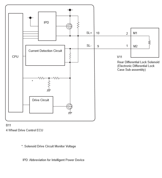
PROCEDURE
Disconnect the B11 4 wheel drive control ECU connector.
Measure the voltage according to the value(s) in the table below.
- Standard Voltage:
-
Tester Connection Condition Specified Condition Click Location & Routing(B11)Location & Routingewd_type=routing;type=c;code=B11
Click Connector(B11)Instrument Panel>Engine Room Main Wire / Heater Blower Wire>4 Wheel Drive Control ECUewd_type=component;type=c;code=B11;pinno=10,9
B11-10 (SL+) - Body ground Ignition switch off Below 1.5 V B11-10 (SL+) - Body ground Ignition switch ON Below 1.5 V B11-9 (SL-) - Body ground Ignition switch off Below 1.5 V B11-9 (SL-) - Body ground Ignition switch ON Below 1.5 V
Connect the B11 4 wheel drive control ECU connector.
- Result:
-
Proceed to OK NG
OK
NG
Disconnect the B11 4 wheel drive control ECU connector.
Measure the resistance according to the value(s) in the table below.
- Standard Resistance:
-
Tester Connection Condition Specified Condition Click Location & Routing(B11)Location & Routingewd_type=routing;type=c;code=B11
Click Connector(B11)Instrument Panel>Engine Room Main Wire / Heater Blower Wire>4 Wheel Drive Control ECUewd_type=component;type=c;code=B11;pinno=10,9
B11-10 (SL+) - Body ground Always 10 kΩ or higher B11-9 (SL-) - Body ground Always 10 kΩ or higher
Connect the B11 4 wheel drive control ECU connector.
- Result:
-
Proceed to OK NG
OK
for LHD: Click hereDrivetrain>JF2BM (TRANSFER / 4WD / AWD)>4WD CONTROL ECU (for LHD)>REMOVAL
for RHD: Click hereDrivetrain>JF2BM (TRANSFER / 4WD / AWD)>4WD CONTROL ECU (for RHD)>REMOVAL
NG
Disconnect the B11 4 wheel drive control ECU connector.
Disconnect the V11 rear differential lock solenoid (electronic differential lock case sub-assembly) connector.
Measure the resistance according to the value(s) in the table below.
- Standard Resistance:
-
Tester Connection Condition Specified Condition Click Location & Routing(B11)Location & Routingewd_type=routing;type=c;code=B11
Click Connector(B11)Instrument Panel>Engine Room Main Wire / Heater Blower Wire>4 Wheel Drive Control ECUewd_type=component;type=c;code=B11;pinno=10,9
B11-10 (SL+) - Body ground Always 10 kΩ or higher B11-9 (SL-) - Body ground Always 10 kΩ or higher
Connect the V11 rear differential lock solenoid (electronic differential lock case sub-assembly) connector.
Connect the B11 4 wheel drive control ECU connector.
- Result:
-
Proceed to OK NG
OK
NG