Home › Engine / Hybrid System › V35A-FTS (ENGINE CONTROL) › SFI SYSTEM
RM38G0E _51 Engine / Hybrid System _100526 V35A-FTS ENGINE CONTROL _0470271 SFI SYSTEM C

V35A-FTS ENGINE CONTROL  SFI SYSTEM  U010187  Lost Communication with TCM Missing Message  


MONITOR DESCRIPTION

The Transmission Control Module (TCM) and ECM perform 2-way communication with each other via the Controller Area Network (CAN). The TCM sends signals to the ECM concerning required engine speed, required engine torque, warning indicators in the combination meter assembly, DTCs and other data. The ECM sends signals to the TCM concerning engine speed, opening angle of the throttle valve, temperature of intake air, temperature of engine coolant, engine torque and other data. If the TCM cannot communicate with the ECM, the TCM will conclude that there is a malfunction in the CAN communication system, illuminate the MIL and store this DTC.

DTC No. Detection Item DTC Detection Condition Trouble Area MIL Note
U010187 Lost Communication with TCM Missing Message All of the following conditions are met for 1.25 seconds or more (1 trip detection logic):
·

Ignition switch ON

·

Battery voltage is 10 V or higher

·

No communication between engine control unit and transmission control unit


·

ECM to TCM circuit

·

TCM

·

ECM


Comes on SAE: U0101

MONITOR STRATEGY

Required Sensors/Components ECM
Frequency of Operation Continuous

CONFIRMATION DRIVING PATTERN

1.

Connect the GTS to the DLC3.

2.

Turn the ignition switch to ON.

3.

Turn the GTS on.

4.

Clear the DTCs (even if no DTCs are stored, perform the clear DTC procedure).

5.

Turn the ignition switch off and wait for at least 30 seconds.

6.

Turn the ignition switch to ON.

7.

Turn the GTS on.

8.

Wait 5 seconds or more.

9.

Enter the following menus: Powertrain / Engine / Trouble Codes.

10.

Read the DTCs.

HINT:
·

If a pending DTC is output, the system is malfunctioning.

·

If a pending DTC is not output, perform the following procedure.


11.

Enter the following menus: Powertrain / Engine / Utility / All Readiness.

12.

Input the DTC: U010187.

13.

Check the DTC judgment result.

GTS Display Description
NORMAL
·

DTC judgment completed

·

System normal


ABNORMAL
·

DTC judgment completed

·

System abnormal


INCOMPLETE
·

DTC judgment not completed

·

Perform driving pattern after confirming DTC enabling conditions


HINT:
·

If the judgment result is NORMAL, the system is normal.

·

If the judgment result is ABNORMAL, the system has a malfunction.


WIRING DIAGRAM
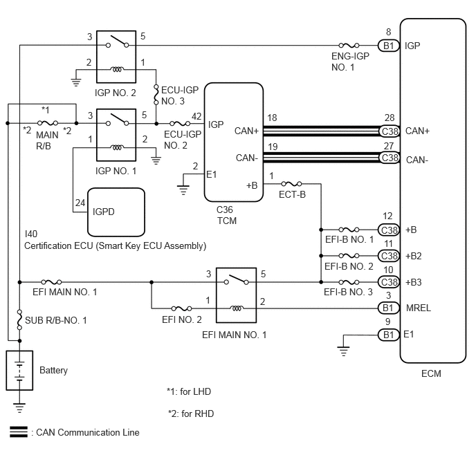
A485845E01
0.594,5.49 1.208,5.688 0.615,0.198 10 false Battery 0.49,4.313 1.573,4.5 1.083,0.188 10 false EFI MAIN NO. 1 3.042,4.958 4.125,5.146 1.083,0.188 10 false EFI MAIN NO. 1 3.104,4.042 3.26,4.229 0.156,0.188 10 false 3 3.094,4.438 3.25,4.625 0.156,0.188 10 false 1 3.927,4.042 4.073,4.229 0.146,0.188 10 false 5 3.917,4.458 4.063,4.646 0.146,0.188 10 false 2 3.26,3.073 3.875,3.271 0.615,0.198 10 false C36 3.271,3.24 3.896,3.563 0.625,0.323 10 false TCM 4.198,2.844 4.969,3.073 0.771,0.229 10 false ECT-B 6.104,3.375 6.719,3.573 0.615,0.198 10 false +B 6.104,3.771 6.719,3.969 0.615,0.198 10 false +B2 6.115,4.552 6.729,4.75 0.615,0.198 10 false MREL 6.073,4.948 6.688,5.146 0.615,0.198 10 false E1 5.771,4.958 6.385,5.156 0.615,0.198 10 false B1 6.344,5.542 6.729,5.885 0.385,0.344 10 false ECM 5.802,4.76 6.01,4.958 0.208,0.198 10 false 9 5.781,2.115 5.99,2.313 0.208,0.198 10 false 27 5.781,3.583 5.99,3.781 0.208,0.198 10 false 11 5.76,3.167 5.969,3.365 0.208,0.198 10 false 12 6.115,2.323 6.729,2.521 0.615,0.198 10 false CAN- 3.552,2.292 4.167,2.49 0.615,0.198 10 false CAN- 6.104,1.885 6.719,2.083 0.615,0.198 10 false CAN+ 3.531,1.885 4.146,2.083 0.615,0.198 10 false CAN+ 4.031,2.125 4.24,2.323 0.208,0.198 10 false 19 5.792,1.688 6,1.885 0.208,0.198 10 false 28 4.021,1.688 4.229,1.885 0.208,0.198 10 false 18 0.375,3.438 0.99,3.635 0.615,0.198 10 false I40 0.365,3.615 3.396,3.823 3.031,0.208 10 false Certification ECU (Smart Key ECU Assembly) 1.396,3.104 2.01,3.302 0.615,0.198 10 false IGPD 1.135,2.969 1.344,3.167 0.208,0.198 10 false 24 1.302,0.854 1.458,1.042 0.156,0.188 10 false 2 2.115,0.854 2.26,1.042 0.146,0.188 10 false 1 1.313,0.469 1.458,0.656 0.146,0.188 10 false 3 2.115,0.458 2.271,0.646 0.156,0.188 10 false 5 1.427,1.313 2.156,1.521 0.729,0.208 10 false IGP NO. 2 2.469,1.938 3.063,2.333 0.594,0.396 10 false ECU-IGP NO. 2 6.094,0.604 6.708,0.802 0.615,0.198 10 false IGP 5.813,0.396 5.958,0.583 0.146,0.188 10 false 8 3.708,2.708 4.323,2.906 0.615,0.198 10 false +B 3.135,1.792 3.75,1.99 0.615,0.198 10 false IGP 4.052,2.563 4.208,2.75 0.156,0.188 10 false 1 2.885,1.667 3.094,1.865 0.208,0.198 10 false 42 5.813,4.365 6.021,4.563 0.208,0.198 10 false 3 0.469,6.427 2.333,6.635 1.865,0.208 10 false : CAN Communication Line 3.104,2.542 3.719,2.74 0.615,0.198 10 false E1 2.906,2.417 3.052,2.604 0.146,0.188 10 false 2 0.375,4.74 1.49,4.969 1.115,0.229 10 false SUB R/B-NO. 1 2.438,4.729 3.521,4.917 1.083,0.188 10 false EFI NO. 2 6.104,4.167 6.719,4.365 0.615,0.198 10 false +B3 5.771,3.979 5.979,4.177 0.208,0.198 10 false 10 4.99,0.76 5.594,1.115 0.604,0.354 10 false ENG-IGP NO. 1 4.896,3.521 5.729,3.896 0.833,0.375 10 false EFI-B NO. 1 4.885,3.927 5.719,4.302 0.833,0.375 10 false EFI-B NO. 2 4.875,4.313 5.708,4.688 0.833,0.375 10 false EFI-B NO. 3 5.76,4.552 6.375,4.75 0.615,0.198 10 false B1 5.771,0.604 6.385,0.802 0.615,0.198 10 false B1 5.74,4.167 6.354,4.365 0.615,0.198 10 false C38 5.74,3.771 6.354,3.969 0.615,0.198 10 false C38 5.74,3.385 6.354,3.583 0.615,0.198 10 false C38 5.75,2.292 6.365,2.49 0.615,0.198 10 false C38 5.75,1.896 6.365,2.094 0.615,0.198 10 false C38 1.438,2.49 2.167,2.698 0.729,0.208 10 false IGP NO. 1 1.323,1.656 1.469,1.844 0.146,0.188 10 false 3 2.135,1.646 2.292,1.833 0.156,0.188 10 false 5 2.146,2.01 2.302,2.198 0.156,0.188 10 false 2 0.625,1.573 0.771,1.76 0.146,0.188 10 false *1 0.542,1.948 1,2.438 0.458,0.49 10 false MAIN R/B 1.323,2.01 1.469,2.198 0.146,0.188 10 false 1 0.344,1.875 0.49,2.063 0.146,0.188 10 false *2 0.948,1.885 1.094,2.073 0.146,0.188 10 false *2 2.51,5.813 3.521,6.031 1.01,0.219 10 false *1: for LHD 2.531,6.146 3.542,6.365 1.01,0.219 10 false *2: for RHD 2.427,1.271 3.031,1.625 0.604,0.354 10 false ECU-IGP NO. 3

CAUTION / NOTICE / HINT

NOTICE:

Inspect the fuses for circuits related to this system before performing the following procedure.


HINT:

Read Freeze Frame Data using the GTS. The ECM records vehicle and driving condition information as Freeze Frame Data the moment a DTC is stored. When troubleshooting, Freeze Frame Data can help determine if the vehicle was moving or stationary, if the engine was warmed up or not, if the air fuel ratio was lean or rich, and other data from the time the malfunction occurred.


PROCEDURE

1.CHECK ANY OTHER DTCS OUTPUT (IN ADDITION TO DTC U010187)
a.

Perform the Health Check using the GTS.


b.

Read the DTCs.

Result:
Result Proceed to
U010187 is output A
U010187 and other DTCs are output B


HINT:

If any DTCs other than U010187 are output, troubleshoot those DTCs first.


A

2.CHECK TERMINAL VOLTAGE (POWER SOURCE OF TCM)

B

GO TO DTC CHART

2.CHECK TERMINAL VOLTAGE (POWER SOURCE OF TCM)
a.

Disconnect the TCM connector.


b.

Turn the ignition switch to ON.


c.

Result:
Proceed to
OK
NG


OK

3.CHECK TERMINAL VOLTAGE (IGP TERMINAL VOLTAGE OF TCM)

NG

3.CHECK TERMINAL VOLTAGE (IGP TERMINAL VOLTAGE OF TCM)
a.

Disconnect the TCM connector.


b.

Turn the ignition switch to ON.


c.

Measure the voltage according to the value(s) in the table below.

Standard Voltage:
Tester Connection Switch Condition Specified Condition

Click Location & Routing(C36)Location & Routing

Click Connector(C36)Engine Compartment>Connecting Wire / Cooling Fan Wire / Engine Wire / Fuel Pump Motor Wire / No. 1 Connecting Wire / No. 10 Engine Wire / No. 2 Connecting Wire / No. 3 Connecting Wire / No. 4 Connecting Wire / Sensor Wire / Turbocharger Wire>Transmission Control ECU Assembly

C36-42 (IGP) - C36-2 (E1) Ignition switch ON 11 to 14 V


Result:
Proceed to
OK
NG


OK

4.CHECK HARNESS AND CONNECTOR (TCM - ECM)

NG

REPAIR OR REPLACE HARNESS OR CONNECTOR (IGP NO. 2 RELAY - TCM)

4.CHECK HARNESS AND CONNECTOR (TCM - ECM)
a.

Disconnect the TCM connector.


b.

Disconnect the ECM connector.


c.

Measure the resistance according to the value(s) in the table below.

Standard Resistance:
Tester Connection Condition Specified Condition

Click Location & Routing(C36,C38)Location & Routing

Click Connector(C36)Engine Compartment>Connecting Wire / Cooling Fan Wire / Engine Wire / Fuel Pump Motor Wire / No. 1 Connecting Wire / No. 10 Engine Wire / No. 2 Connecting Wire / No. 3 Connecting Wire / No. 4 Connecting Wire / Sensor Wire / Turbocharger Wire>Transmission Control ECU Assembly

Click Connector(C38)Engine Compartment>Connecting Wire / Cooling Fan Wire / Engine Wire / Fuel Pump Motor Wire / No. 1 Connecting Wire / No. 10 Engine Wire / No. 2 Connecting Wire / No. 3 Connecting Wire / No. 4 Connecting Wire / Sensor Wire / Turbocharger Wire>ECM

C36-18 (CAN+) - C38-28 (CAN+) Always Below 1 Ω
C36-19 (CAN-) - C38-27 (CAN-) Always Below 1 Ω
C36-18 (CAN+) or C38-28 (CAN+) - Body ground and other terminals Always 10 kΩ or higher
C36-19 (CAN-) or C38-27 (CAN-) - Body ground and other terminals Always 10 kΩ or higher


Result:
Proceed to
OK
NG


OK

5.REPLACE TCM

NG

REPAIR OR REPLACE HARNESS OR CONNECTOR

5.REPLACE TCM

NEXT

6.CLEAR DTC
6.CLEAR DTC
a.

Clear the DTCs.

Powertrain > Engine > Clear DTCs
50002 372

b.

Turn the ignition switch off and wait for at least 30 seconds.


Result:
Proceed to
NEXT


NEXT

7.CHECK WHETHER DTC OUTPUT RECURS (DTC U010187)
a.

Drive the vehicle in accordance with the driving pattern described in the Confirmation Driving Pattern.


b.

Read the DTCs.

Powertrain > Engine > Trouble Codes
50001 372
Result:
Result Proceed to
DTCs are not output A
U010187 is output B


A

END

B