V35A-FTS INTAKE / EXHAUST TURBOCHARGER INSTALLATION
CAUTION / NOTICE / HINT
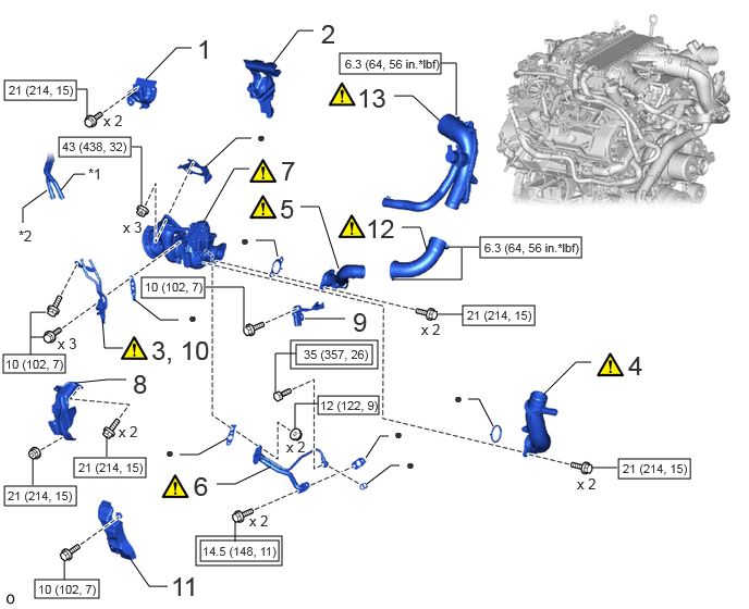
| Procedure | Part Name Code |

|

|

|
|
|---|---|---|---|---|---|
| 1 | NO. 1 TURBO INSULATOR STAY | 17273 | - | - | - |
| 2 | NO. 4 ENGINE COVER | 12614A | - | - | - |
| 3 | INSTALL NO. 1 TURBO WATER PIPE SUB-ASSEMBLY | 16027 | ( ) |
- | - |
| 4 | COMPRESSOR INLET ELBOW SUB-ASSEMBLY | 17203B | () |
- | - |
| 5 | NO. 1 COMPRESSOR OUTLET ELBOW | 17275B | () |
- | - |
| 6 | TURBO OIL INLET PIPE SUB-ASSEMBLY RH | 15407G | () |
- | - |
| 7 | NO. 2 TURBOCHARGER SUB-ASSEMBLY | 17208 | () |
- | - |
| 8 | NO. 1 TURBO INSULATOR | 17271 | - | - | - |
| 9 | NO. 10 ENGINE WIRE | 8212B | - | - | - |
| 10 | CONNECT NO. 1 TURBO WATER PIPE SUB-ASSEMBLY | 16027 | () |
- | - |
| 11 | NO. 1 ENGINE COVER SUB-ASSEMBLY | 12601F | - | - | - |
| 12 | NO. 1 AIR HOSE | 17341M | () |
- | - |
| 13 | NO. 1 AIR TUBE ASSEMBLY | - | () |
- | - |
| *1 | NO. 1 TURBO WATER HOSE | *2 | NO. 2 TURBO WATER HOSE |

|
Tightening torque for "Major areas involving basic vehicle performance such as moving/turning/stopping": N*m (kgf*cm, ft.*lbf) |

|
N*m (kgf*cm, ft.*lbf): Specified torque |
| ● | Non-reusable part | - | - |
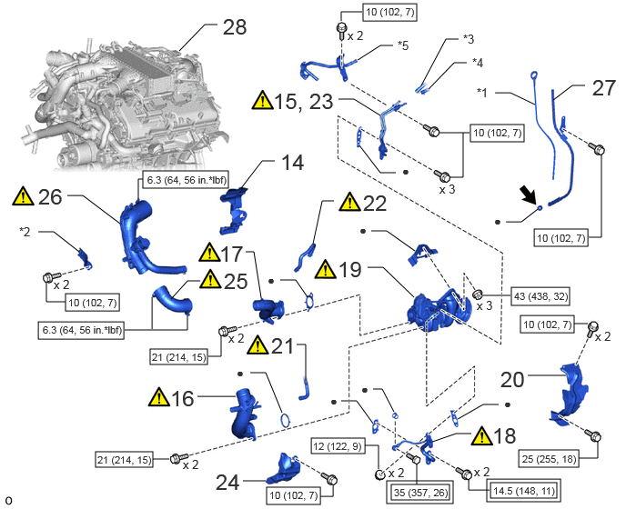
| Procedure | Part Name Code |
|
|
|
|
|---|---|---|---|---|---|
| 14 | NO. 5 ENGINE COVER | 12615A | - | - | - |
| 15 | INSTALL NO. 2 TURBO WATER PIPE SUB-ASSEMBLY | 16028 | () |
- | - |
| 16 | NO. 2 COMPRESSOR INLET ELBOW SUB-ASSEMBLY | 17204 | () |
- | - |
| 17 | NO. 2 COMPRESSOR OUTLET ELBOW | 17285A | () |
- | - |
| 18 | TURBO OIL INLET PIPE SUB-ASSEMBLY LH | 15408G | () |
- | - |
| 19 | NO. 1 TURBOCHARGER SUB-ASSEMBLY | 17201A | () |
- | - |
| 20 | NO. 3 TURBO INSULATOR | 17288 | - | - | - |
| 21 | NO. 4 FUEL VAPOR FEED HOSE | 2382A | () |
- | - |
| 22 | NO. 6 AIR HOSE | 17346G | () |
- | - |
| 23 | CONNECT NO. 2 TURBO WATER PIPE SUB-ASSEMBLY | 16028 | () |
- | - |
| 24 | NO. 2 ENGINE COVER SUB-ASSEMBLY | 12602E | - | - | - |
| 25 | NO. 3 AIR HOSE | 17343N | () |
- | - |
| 26 | NO. 2 AIR TUBE ASSEMBLY | - | () |
- | - |
| 27 | ENGINE OIL LEVEL DIPSTICK GUIDE | 11452 | - | - | - |
| 28 | ENGINE STAND | - | - | - | - |
| *1 | ENGINE OIL LEVEL DIPSTICK | *2 | NO. 2 AIR TUBE SUPPORT |
| *3 | NO. 3 TURBO WATER HOSE | *4 | NO. 4 TURBO WATER HOSE |
| *5 | FUEL VAPOR FEED PIPE ASSEMBLY | - | - |
|
|
Tightening torque for "Major areas involving basic vehicle performance such as moving/turning/stopping": N*m (kgf*cm, ft.*lbf) |
|
N*m (kgf*cm, ft.*lbf): Specified torque |
| ● | Non-reusable part |

|
Engine oil |
CAUTION / NOTICE / HINT
- NOTICE:
-
This procedure includes the installation of small-head bolts. Refer to Small-Head Bolts of Basic Repair Hint to identify the small-head bolts.
-
Click hereGeneral>INTRODUCTION>REPAIR INSTRUCTION>PRECAUTION
- HINT:
-
Perform "Inspection After Repairs" after replacing the turbocharger sub-assembly.
-
Click hereEngine / Hybrid System>V35A-FTS (ENGINE CONTROL)>SFI SYSTEM>INITIALIZATION
PROCEDURE

 17273 1.INSTALL NO. 1 TURBO INSULATOR STAY
- Torque:
- 21 N*m (214 kgf*cm, 15 ft.*lbf)
12614A 2.INSTALL NO. 4 ENGINE COVER
16027 3.INSTALL NO. 1 TURBO WATER PIPE SUB-ASSEMBLY
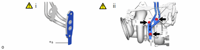
| *a | Protrusion | - | - |
Install a new gasket as shown in the illustration.
- NOTICE:
-
·
The claws of the gasket must face the No. 1 turbo water pipe sub-assembly.
·Install the gasket so that its protrusion faces down as shown in the illustration.
Install the No. 1 turbo water pipe sub-assembly to the No. 2 turbocharger sub-assembly with the 3 bolts in the order shown in the illustration.
- Torque:
- 10 N*m (102 kgf*cm, 7 ft.*lbf)
17203B 4.INSTALL COMPRESSOR INLET ELBOW SUB-ASSEMBLY
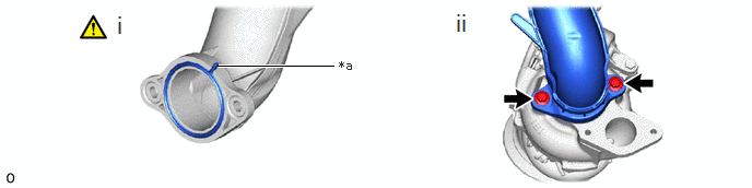
| *a | Protrusion | - | - |
Install a new gasket to the compressor inlet elbow sub-assembly aligning the groove on the compressor inlet elbow sub-assembly with the protrusion of the gasket.
- NOTICE:
-
Check that the gasket is securely fitted into the groove on the compressor inlet elbow sub-assembly.
Install the compressor inlet elbow sub-assembly to the No. 2 turbocharger sub-assembly with the 2 bolts.
- Torque:
- 21 N*m (214 kgf*cm, 15 ft.*lbf)
17275B 5.INSTALL NO. 1 COMPRESSOR OUTLET ELBOW
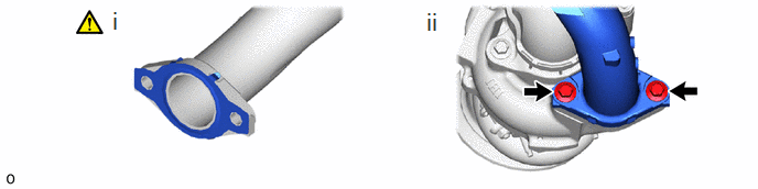
Install a new gasket to the No. 1 compressor outlet elbow.
- NOTICE:
-
The claws of the gasket must face the No. 1 compressor outlet elbow.
Install the No. 1 compressor outlet elbow to the No. 2 turbocharger sub-assembly with the 2 bolts.
- Torque:
- 21 N*m (214 kgf*cm, 15 ft.*lbf)
15407G 6.INSTALL TURBO OIL INLET PIPE SUB-ASSEMBLY RH
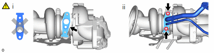
Install a new gasket.
- NOTICE:
-
Do not install the gasket upside down.
Install the turbo oil inlet pipe sub-assembly RH with the 2 nuts.
- Torque:
- 12 N*m (122 kgf*cm, 9 ft.*lbf)
17208 7.INSTALL NO. 2 TURBOCHARGER SUB-ASSEMBLY
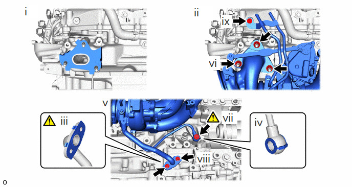
Install a new gasket to the cylinder head sub-assembly.
Temporarily install the No. 2 turbocharger sub-assembly with the 3 nuts and bolt.
Install a new gasket to the turbo oil inlet pipe sub-assembly RH.
- NOTICE:
-
The claws of the gasket must face the turbo oil inlet pipe sub-assembly RH.
Install a new gasket to the union bolt side.
Temporarily install the turbo oil inlet pipe sub-assembly RH with the union bolt and 2 bolts.
Tighten the 3 nuts.
- Torque:
- 43 N*m (438 kgf*cm, 32 ft.*lbf)
Tighten the union bolt.
- Torque:
- 35 N*m (357 kgf*cm, 26 ft.*lbf)
- NOTICE:
-
If the connecting part of the union bolt gasket is cracked, remove the connecting part.
Tighten the 2 bolts.
- Torque:
- 14.5 N*m (148 kgf*cm, 11 ft.*lbf)
Tighten the bolt.
- Torque:
- 10 N*m (102 kgf*cm, 7 ft.*lbf)
17271 8.INSTALL NO. 1 TURBO INSULATOR
- Torque:
- 21 N*m (214 kgf*cm, 15 ft.*lbf)
8212B 9.INSTALL NO. 10 ENGINE WIRE
- Torque:
- 10 N*m (102 kgf*cm, 7 ft.*lbf)
16027 10.CONNECT NO. 1 TURBO WATER PIPE SUB-ASSEMBLY
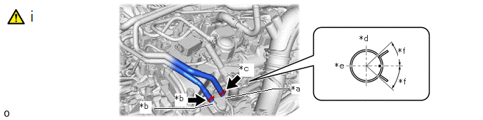
| *a | Paint Mark (Yellow) | *b | Paint Mark (White) |
| *c | Paint Mark (Pink) | *d | Front Side |
| *e | LH Side | *f | 45° |
Connect the No. 1 turbo water hose and No. 2 turbo water hose to the No. 1 turbo water pipe sub-assembly and slide the 2 clamps to secure the hoses.
- NOTICE:
-
·
Be sure to correctly connect the No. 1 turbo water hose and No. 2 turbo water hose. Incorrect installation may damage the turbocharger sub-assembly.
·Align the hose clip at the locations shown in the illustration.
12601F 11.INSTALL NO. 1 ENGINE COVER SUB-ASSEMBLY
- Torque:
- 10 N*m (102 kgf*cm, 7 ft.*lbf)
17341M 12.INSTALL NO. 1 AIR HOSE
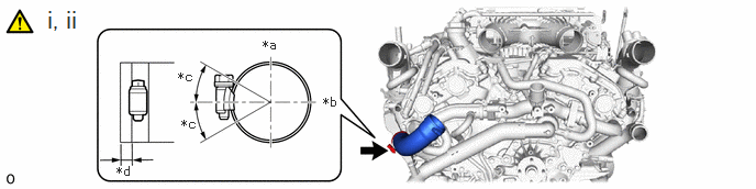
| *a | Upper Side | *b | RH Side |
| *c | 30° | *d | 3 to 7 mm (0.118 to 0.276 in.) |
Install the hose clamp and No. 1 air hose to the No. 1 compressor outlet elbow.
- NOTICE:
-
Before installing the No. 1 air hose and No. 1 compressor outlet elbow connections, clean off any oil.
Tighten the hose clamp as shown in the illustration.
- Torque:
- 6.3 N*m (64 kgf*cm, 56 in.*lbf)
13.INSTALL NO. 1 AIR TUBE ASSEMBLY
|
|
Click here() |
12615A 14.INSTALL NO. 5 ENGINE COVER
16028 15.INSTALL NO. 2 TURBO WATER PIPE SUB-ASSEMBLY
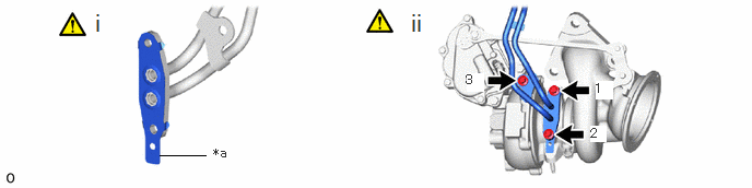
| *a | Protrusion | - | - |
Install a new gasket as shown in the illustration.
- NOTICE:
-
·
The claws of the gasket must face the No. 2 turbo water pipe sub-assembly.
·Install the gasket so that its protrusion faces down as shown in the illustration.
Install the No. 2 turbo water pipe sub-assembly to the No. 1 turbocharger sub-assembly with the 3 bolts in the order shown in the illustration.
- Torque:
- 10 N*m (102 kgf*cm, 7 ft.*lbf)
17204 16.INSTALL NO. 2 COMPRESSOR INLET ELBOW SUB-ASSEMBLY
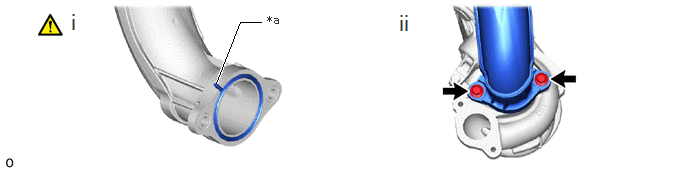
| *a | Protrusion | - | - |
Install a new gasket to the No. 2 compressor inlet elbow sub-assembly aligning the groove on the No. 2 compressor inlet elbow sub-assembly with the protrusion of the gasket.
- NOTICE:
-
Check that the gasket is securely fitted into the groove on the No. 2 compressor inlet elbow sub-assembly.
Install the No. 2 compressor inlet elbow sub-assembly to the No. 1 turbocharger sub-assembly with the 2 bolts.
- Torque:
- 21 N*m (214 kgf*cm, 15 ft.*lbf)
17285A 17.INSTALL NO. 2 COMPRESSOR OUTLET ELBOW
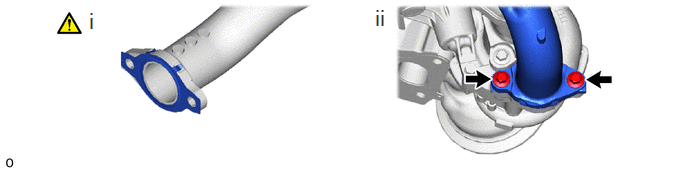
Install a new gasket to the No. 2 compressor outlet elbow.
- NOTICE:
-
The claws of the gasket must face the No. 2 compressor outlet elbow.
Install the No. 2 compressor outlet elbow to the No. 1 turbocharger sub-assembly with the 2 bolts.
- Torque:
- 21 N*m (214 kgf*cm, 15 ft.*lbf)
15408G 18.INSTALL TURBO OIL INLET PIPE SUB-ASSEMBLY LH
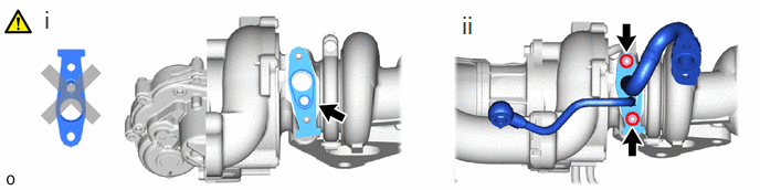
Install a new gasket.
- NOTICE:
-
Do not install the gasket upside down.
Install the turbo oil inlet pipe sub-assembly LH with the 2 nuts.
- Torque:
- 12 N*m (122 kgf*cm, 9 ft.*lbf)
17201A 19.INSTALL NO. 1 TURBOCHARGER SUB-ASSEMBLY
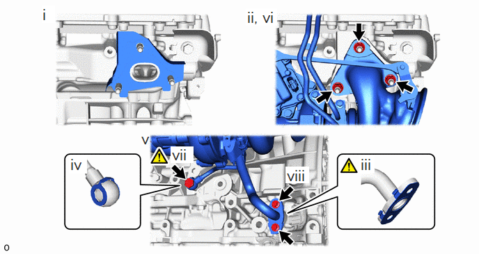
Install a new gasket to the cylinder head sub-assembly.
Temporarily install the No. 1 turbocharger sub-assembly with the 3 nuts.
Install a new gasket to the turbo oil inlet pipe sub-assembly LH.
- NOTICE:
-
The claws of the gasket must face the turbo oil inlet pipe sub-assembly LH.
Install a new gasket to the union bolt side.
Temporarily install the turbo oil inlet pipe sub-assembly LH with the union bolt and 2 bolts.
Tighten the 3 nuts.
- Torque:
- 43 N*m (438 kgf*cm, 32 ft.*lbf)
Tighten the union bolt.
- Torque:
- 35 N*m (357 kgf*cm, 26 ft.*lbf)
- NOTICE:
-
If the connecting part of the union bolt gasket is cracked, remove the connecting part.
Tighten the 2 bolts.
- Torque:
- 14.5 N*m (148 kgf*cm, 11 ft.*lbf)
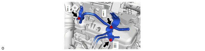
Install the fuel vapor feed pipe assembly to the cylinder head cover LH with the 2 bolts.
- Torque:
- 10 N*m (102 kgf*cm, 7 ft.*lbf)
Connect the No. 2 turbo water pipe sub-assembly to the fuel vapor feed pipe assembly with the bolt.
- Torque:
- 10 N*m (102 kgf*cm, 7 ft.*lbf)
17288 20.INSTALL NO. 3 TURBO INSULATOR
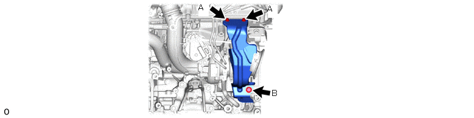
- Torque:
- for bolt A : 10 N*m (102 kgf*cm, 7 ft.*lbf)
- for bolt B : 25 N*m (255 kgf*cm, 18 ft.*lbf)
2382A 21.CONNECT NO. 4 FUEL VAPOR FEED HOSE
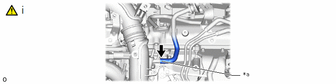
| *a | Paint Mark (Yellow) | - | - |
Connect the No. 4 fuel vapor feed hose.
17346G 22.INSTALL NO. 6 AIR HOSE
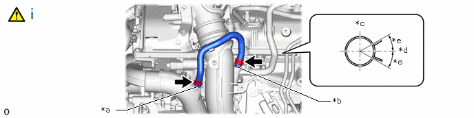
| *a | Paint Mark (White) | *b | Paint Mark (Yellow) |
| *c | Rear Side | *d | LH Side |
| *e | 30° | - | - |
Install the No. 6 air hose and slide the 2 clamps to secure the hoses.
- NOTICE:
-
Align the hose clip at the locations shown in the illustration.
16028 23.CONNECT NO. 2 TURBO WATER PIPE SUB-ASSEMBLY
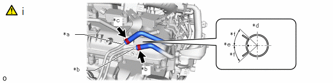
| *a | Paint Mark (Yellow) | *b | Paint Mark (White) |
| *c | Paint Mark (Pink) | *d | Upper Side |
| *e | LH Side | *f | 45° |
Connect the No. 3 turbo water hose and No. 4 turbo water hose to the No. 2 turbo water pipe sub-assembly and slide the 2 clamps to secure the hoses.
- NOTICE:
-
·
Be sure to correctly connect the No. 3 turbo water hose and No. 4 turbo water hose. Incorrect installation may damage the turbocharger sub-assembly.
·Align the hose clip at the locations shown in the illustration.
12602E 24.INSTALL NO. 2 ENGINE COVER SUB-ASSEMBLY
- Torque:
- 10 N*m (102 kgf*cm, 7 ft.*lbf)
17343N 25.INSTALL NO. 3 AIR HOSE
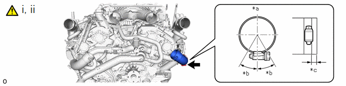
| *a | Upper Side | *b | 30° |
| *c | 3 to 7 mm (0.118 to 0.276 in.) | - | - |
Install the hose clamp and No. 3 air hose to the No. 2 compressor outlet elbow.
- NOTICE:
-
Before installing the No. 3 air hose and No. 2 compressor outlet elbow connections, clean off any oil.
Tighten the hose clamp as shown in the illustration.
- Torque:
- 6.3 N*m (64 kgf*cm, 56 in.*lbf)
26.INSTALL NO. 2 AIR TUBE ASSEMBLY
|
|
Click here() |
11452 27.INSTALL ENGINE OIL LEVEL DIPSTICK GUIDE
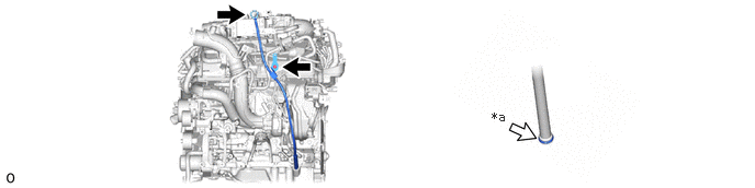
| *a | Apply a light coat of engine oil | - | - |
- Torque:
- 10 N*m (102 kgf*cm, 7 ft.*lbf)
28.REMOVE ENGINE STAND
29.PERFORM INITIALIZATION
Perform "Inspection After Repair" after replacing the turbocharger sub-assembly.
Click hereEngine / Hybrid System>V35A-FTS (ENGINE CONTROL)>SFI SYSTEM>INITIALIZATION