V35A-FTS INTAKE / EXHAUST INTERCOOLER INSTALLATION
CAUTION / NOTICE / HINT
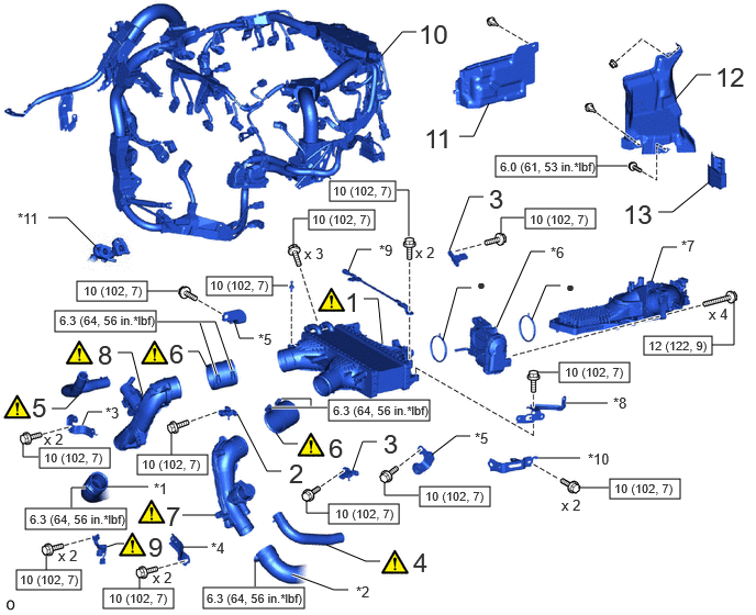
| Procedure | Part Name Code |

|

|

|
|
|---|---|---|---|---|---|
| 1 | INTERCOOLER ASSEMBLY | 17940D | ( ) |
- | - |
| 2 | NO. 2 TURBO PRESSURE SENSOR | 89421L | - | - | - |
| 3 | NO. 1 TURBO PRESSURE SENSOR | 89421K | - | - | - |
| 4 | NO. 4 AIR HOSE | 17344L | () |
- | - |
| 5 | NO. 2 AIR HOSE | 17342M | () |
- | - |
| 6 | NO. 5 AIR HOSE | 17345M | () |
- | - |
| 7 | NO. 2 AIR TUBE ASSEMBLY | - | () |
- | - |
| 8 | NO. 1 AIR TUBE ASSEMBLY | - | () |
- | - |
| 9 | COOLING FAN WIRE | 16364A | () |
- | - |
| 10 | ENGINE WIRE | 82121 | - | - | - |
| 11 | ENGINE SIDE UNDER COVER RH | 51448M | - | - | - |
| 12 | REAR ENGINE SIDE UNDER COVER ASSEMBLY LH | 51470C | - | - | - |
| 13 | UPPER ENGINE SIDE UNDER COVER PLATE LH | 51478C | - | - | - |
| *1 | NO. 1 AIR HOSE | *2 | NO. 3 AIR HOSE |
| *3 | NO. 1 AIR TUBE SUPPORT | *4 | NO. 2 AIR TUBE SUPPORT |
| *5 | INTERCOOLER SUPPORT BRACKET | *6 | THROTTLE WITH THROTTLE POSITION SENSOR BODY ASSEMBLY |
| *7 | INTAKE AIR SURGE TANK ASSEMBLY | *8 | PURGE PRESSURE SENSOR BRACKET |
| *9 | NO. 1 V-BANK COVER BRACKET | *10 | WIRE HARNESS CLAMP BRACKET |
| *11 | INTERCOOLER COOLING WATER PIPE ASSEMBLY | - | - |

|
N*m (kgf*cm, ft.*lbf): Specified torque | - | - |
| ● | Non-reusable part | - | - |
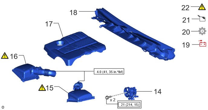
| Procedure | Part Name Code |
|
|
|
|
|---|---|---|---|---|---|
| 14 | VANE PUMP ASSEMBLY | 44310 | - | - | - |
| 15 | AIR CLEANER CAP WITH AIR CLEANER HOSE ASSEMBLY LH | 17735 | () |
- | - |
| 16 | AIR CLEANER CAP WITH AIR CLEANER HOSE ASSEMBLY RH | 17735 | () |
- | - |
| 17 | V-BANK COVER SUB-ASSEMBLY | 11209 | - | - | - |
| 18 | COWL TOP VENTILATOR LOUVER SUB-ASSEMBLY | 55708 | - | - | - |
| 19 | CONNECT CABLE TO NEGATIVE BATTERY TERMINAL | - | - | - | - |
| 20 | INITIALIZATION AFTER RECONNECTING BATTERY TERMINAL | - | - | - | () |
| 21 | ADD COOLANT (for Intercooler) | - | - | () |
- |
| 22 | INSPECT FOR COOLANT LEAK (for Intercooler) | - | () |
- | - |

|
Tightening torque for "Major areas involving basic vehicle performance such as moving/turning/stopping": N*m (kgf*cm, ft.*lbf) |
|
N*m (kgf*cm, ft.*lbf): Specified torque |
CAUTION / NOTICE / HINT
- NOTICE:
-
This procedure includes the installation of small-head bolts. Refer to Small-Head Bolts of Basic Repair Hint to identify the small-head bolts.
-
Click hereGeneral>INTRODUCTION>REPAIR INSTRUCTION>PRECAUTION
PROCEDURE

 17940D 1.INSTALL INTERCOOLER ASSEMBLY
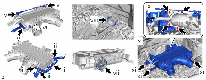
Install the intercooler support bracket to the intercooler assembly with the bolt.
- Torque:
- 10 N*m (102 kgf*cm, 7 ft.*lbf)
Install the purge pressure sensor bracket to the intercooler assembly with the bolt.
- Torque:
- 10 N*m (102 kgf*cm, 7 ft.*lbf)
Install the wire harness clamp bracket with the 2 bolts.
- Torque:
- 10 N*m (102 kgf*cm, 7 ft.*lbf)
Install the intercooler support bracket to the intercooler assembly with the bolt.
- Torque:
- 10 N*m (102 kgf*cm, 7 ft.*lbf)
Install the No. 1 V-bank cover bracket to the intercooler assembly with the 2 bolts.
- Torque:
- 10 N*m (102 kgf*cm, 7 ft.*lbf)
Install the bolt to the intercooler assembly.
- Torque:
- 10 N*m (102 kgf*cm, 7 ft.*lbf)
Install a new gasket to the intercooler assembly as shown in the illustration.
Install a new gasket to the intake air surge tank assembly as shown in the illustration.
Temporarily install the intercooler assembly and throttle with throttle position sensor assembly with the 7 bolts.
Tighten the 4 bolts.
- Torque:
- 12 N*m (122 kgf*cm, 9 ft.*lbf)
Tighten the 3 bolts.
- Torque:
- 10 N*m (102 kgf*cm, 7 ft.*lbf)
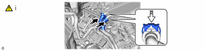

|
Connect the Intercooler Cooling Water Pipe Assembly |

|
Insert the Retainer in the Direction of the Arrow Shown in the Illustration. |
Connect the intercooler cooling water pipe assembly to the intercooler assembly and slide the retainer to secure it as shown in the illustration.
- NOTICE:
-
·
Push in the retainer until a click sound is heard.
·Pull on the intercooler cooling water pipe assembly to confirm that the hose is securely connected.
·If there is foreign matter on the union or the O-ring, clean it with water and finger scouring.
89421L 2.INSTALL NO. 2 TURBO PRESSURE SENSOR
89421K 3.INSTALL NO. 1 TURBO PRESSURE SENSOR
17344L 4.INSTALL NO. 4 AIR HOSE
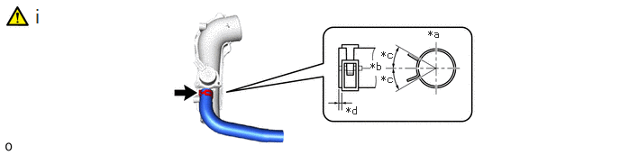
| *a | Upper Side | *b | Front Side |
| *c | 30° | *d | 1 to 6 mm (0.0394 to 0.236 in.) |
Connect the No. 4 air hose to the No. 2 air tube assembly and slide the hose clip to secure it.
- NOTICE:
-
Align the hose clip at the locations shown in the illustration.
17342M 5.INSTALL NO. 2 AIR HOSE
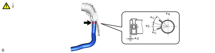
| *a | Upper Side | *b | Rear Side |
| *c | 30° | *d | 1 to 6 mm (0.0394 to 0.236 in.) |
Connect the No. 2 air hose to the No. 1 air tube assembly and slide the hose clip to secure it.
- NOTICE:
-
Align the hose clip at the locations shown in the illustration.
17345M 6.INSTALL NO. 5 AIR HOSE
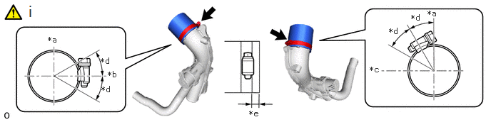
| *a | Upper Side | *b | LH Side |
| *c | RH Side | *d | 30° |
| *e | 3 to 7 mm (0.118 to 0.276 in.) | - | - |
Install the 2 No. 5 air hoses to the No. 1 air tube assembly and No. 2 air tube assembly with the 2 hose clamps.
- Torque:
- 6.3 N*m (64 kgf*cm, 56 in.*lbf)
- NOTICE:
-
Align the hose clamp at the locations shown in the illustration.
7.INSTALL NO. 2 AIR TUBE ASSEMBLY
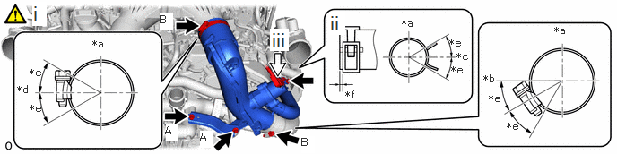
| *a | Upper Side | *b | Front Side |
| *c | LH Side | *d | RH Side |
| *e | 30° | *f | 1 to 6 mm (0.0394 to 0.236 in.) |
Install the No. 2 air tube assembly and No. 2 air tube support with the 2 clamps and 2 bolts.
- Torque:
- for bolt A : 10 N*m (102 kgf*cm, 7 ft.*lbf)
- for hose clamp B : 6.3 N*m (64 kgf*cm, 56 in.*lbf)
- NOTICE:
-
Align the hose clamp at the locations shown in the illustration.
Connect the No. 4 air hose and slide the hose clip to secure it.
- NOTICE:
-
Align the hose clip at the locations shown in the illustration.
Connect the connector.
8.INSTALL NO. 1 AIR TUBE ASSEMBLY
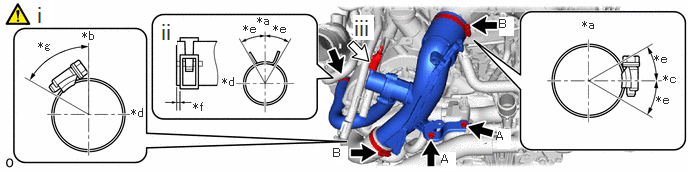
| *a | Upper Side | *b | Front Side |
| *c | LH Side | *d | RH Side |
| *e | 30° | *f | 1 to 6 mm (0.0394 to 0.236 in.) |
| *g | 60° | - | - |
Install the No. 1 air tube assembly and No. 1 air tube support with the 2 clamps and 2 bolts.
- Torque:
- for bolt A : 10 N*m (102 kgf*cm, 7 ft.*lbf)
- for hose clamp B : 6.3 N*m (64 kgf*cm, 56 in.*lbf)
- NOTICE:
-
Align the hose clamp at the locations shown in the illustration.
Connect the No. 2 air hose and slide the hose clip to secure it.
- NOTICE:
-
Align the hose clip at the locations shown in the illustration.
Connect the connector.
16364A 9.INSTALL COOLING FAN WIRE
|
|
Click here() |
82121 10.CONNECT ENGINE WIRE
for LHD:
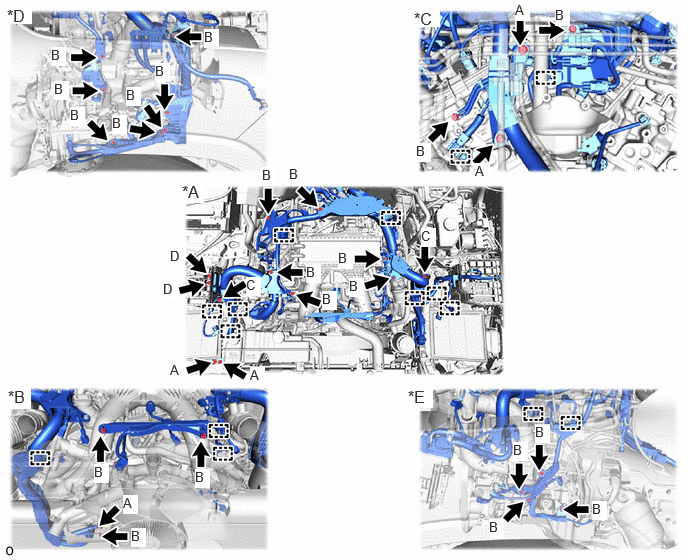
| *A | for Upper Side | *B | for Front Side |
| *C | for Rear Side | *D | for RH Side |
| *E | for LH Side | - | - |
- Torque:
- for bolt A : 20 N*m (204 kgf*cm, 15 ft.*lbf)
- for bolt B : 10 N*m (102 kgf*cm, 7 ft.*lbf)
- for nut C : 10 N*m (102 kgf*cm, 7 ft.*lbf)
- for nut D : 8.0 N*m (82 kgf*cm, 71 in.*lbf)
for RHD:
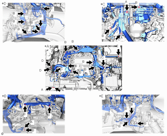
| *A | for Upper Side | *B | for Front Side |
| *C | for Rear Side | *D | for RH Side |
| *E | for LH Side | - | - |
- Torque:
- for bolt A : 20 N*m (204 kgf*cm, 15 ft.*lbf)
- for bolt B : 10 N*m (102 kgf*cm, 7 ft.*lbf)
- for nut C : 10 N*m (102 kgf*cm, 7 ft.*lbf)
- for nut D : 8.0 N*m (82 kgf*cm, 71 in.*lbf)
- for nut E : 7.5 N*m (76 kgf*cm, 66 in.*lbf)
51448M 11.INSTALL ENGINE SIDE UNDER COVER RH
51470C 12.INSTALL REAR ENGINE SIDE UNDER COVER ASSEMBLY LH
51478C 13.INSTALL UPPER ENGINE SIDE UNDER COVER PLATE LH
44310 14.CONNECT VANE PUMP ASSEMBLY
17735 15.INSTALL AIR CLEANER CAP WITH AIR CLEANER HOSE ASSEMBLY LH
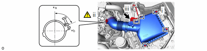
| *a | Upper Side | *b | RH Side |
Attach the 4 clamps and install the air cleaner cap with air cleaner hose assembly LH.
Tighten the hose clamp in the position shown in the illustration.
- Torque:
- 4.0 N*m (41 kgf*cm, 35 in.*lbf)
- NOTICE:
-
Make sure that the clamp bolt of the hose clamp are within the area shown in the illustration.
Attach the clamp and connect the connector.
17735 16.INSTALL AIR CLEANER CAP WITH AIR CLEANER HOSE ASSEMBLY RH
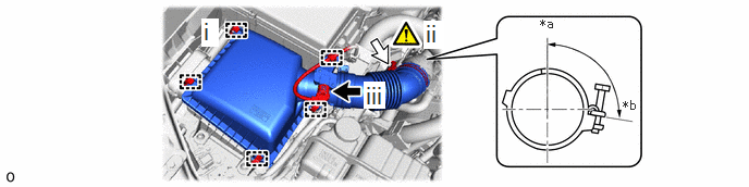
| *a | Upper Side | *b | RH Side |
Attach the 4 clamps and install the air cleaner cap with air cleaner hose assembly RH.
Tighten the hose clamp in the position shown in the illustration.
- Torque:
- 4.0 N*m (41 kgf*cm, 35 in.*lbf)
- NOTICE:
-
Make sure that the clamp bolt of the hose clamp are within the area shown in the illustration.
Attach the clamp and connect the connector.
11209 17.INSTALL V-BANK COVER SUB-ASSEMBLY
55708 18.INSTALL COWL TOP VENTILATOR LOUVER SUB-ASSEMBLY
19.CONNECT CABLE TO NEGATIVE BATTERY TERMINAL
20. INITIALIZATION AFTER RECONNECTING BATTERY TERMINAL
Click hereGeneral>SETUP>WHEN DISCONNECTING OR RECONNECTING BATTERY TERMINAL>WORK PROCEDURE
- HINT:
-
When disconnecting and reconnecting the battery, there is an automatic learning function that completes learning when the respective system is used.
-
Click hereGeneral>SETUP>WHEN DISCONNECTING OR RECONNECTING BATTERY TERMINAL>AUTOMATIC LEARNING CHART
21.ADD COOLANT (for Intercooler)
22.INSPECT FOR COOLANT LEAK (for Intercooler)