PARK ASSIST / MONITORING MULTI-TERRAIN MONITOR SYSTEM "CHK" message(s) are displayed on the SIGNAL CHECK screen.
DESCRIPTION
On the Signal Check (*) screen, it is possible to check if the signals sent to the parking assist ECU are normal.
Click hereAudio / Visual / Telematics>PARK ASSIST / MONITORING>MULTI-TERRAIN MONITOR SYSTEM>DIAGNOSIS SYSTEM
- HINT:
-
·
On the Signal Check (*) screen, "OK" (blue) is displayed for items with a normal inspection result or input state.
·On the Signal Check (*) screen, "CHK" (red) is displayed for items with an abnormal inspection result or input state.
·Displayed items may differ depending on vehicle specifications.
| Item | Signal Input Method | Detail | DTC Output When Abnormal Result is Displayed | Signal Receiver |
|---|---|---|---|---|
| CAN | CAN communication | CAN communication signal | DTC is output | Related ECUs |
| CAMERA SW | Vehicle wire harness | Multi-terrain monitor switch signal input state | DTC is not output | Multi-terrain monitor switch (trip switch) |
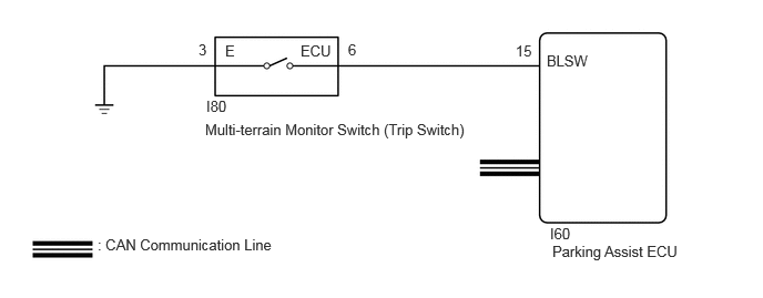
WIRING DIAGRAM
CAUTION / NOTICE / HINT
- NOTICE:
-
·
When "!" mark is displayed on the multi-display assembly after the cable is disconnected from the negative (-) battery terminal, correct the steering angle neutral point.
Click hereAudio / Visual / Telematics>PARK ASSIST / MONITORING>MULTI-TERRAIN MONITOR SYSTEM>INITIALIZATION
·Depending on the parts that are replaced or operations that are performed during vehicle inspection or maintenance, calibration of other systems as well as the multi-terrain monitor system may be needed.
Click hereAudio / Visual / Telematics>PARK ASSIST / MONITORING>MULTI-TERRAIN MONITOR SYSTEM>CALIBRATION
PROCEDURE
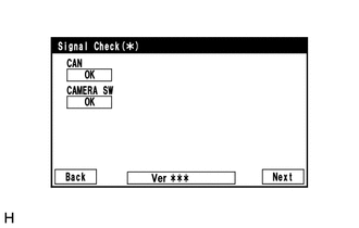
Check which items display on the signal check screen.
- Result:
-
Result Proceed to "CAMERA SW" displays "CHK" (red) A "CAN" displays "CHK" (red) B
A
B
Click herePower Source / Network>NETWORKING>CAN COMMUNICATION SYSTEM>HOW TO PROCEED WITH TROUBLESHOOTING
Disconnect the I80 multi-terrain monitor switch (trip switch) connector.
Disconnect the I60 parking assist ECU connector.
Measure the resistance according to the value(s) in the table below.
- Standard Resistance:
-
Tester Connection Condition Specified Condition Click Location & Routing(I60,I80)Location & Routingewd_type=routing;type=c,c;code=I60,I80
I60-15 (BLSW) - I80-6 (ECU) Always Below 1 Ω I80-3 (E) - Body ground Always Below 1 Ω I60-15 (BLSW) - Body ground Always 10 kΩ or higher
- Result:
-
Proceed to OK NG
OK
NG
Click hereAudio / Visual / Telematics>PARK ASSIST / MONITORING>PANORAMIC VIEW MONITOR SWITCH>INSPECTION
- Result:
-
Proceed to OK NG
OK
for LHD:
Click hereAudio / Visual / Telematics>PARK ASSIST / MONITORING>PARKING ASSIST ECU (for LHD)>REMOVAL
for RHD:
Click hereAudio / Visual / Telematics>PARK ASSIST / MONITORING>PARKING ASSIST ECU (for RHD)>REMOVAL
NG
Click hereAudio / Visual / Telematics>PARK ASSIST / MONITORING>PANORAMIC VIEW MONITOR SWITCH>REMOVAL