Home › Drivetrain › AJA0F (AUTOMATIC TRANSMISSION / TRANSAXLE) › AUTOMATIC TRANSMISSION SYSTEM (for V35A-FTS)
RM38G0E _52 Drivetrain _100435 AJA0F AUTOMATIC TRANSMISSION / TRANSAXLE _0472752 AUTOMATIC TRANSMISSION SYSTEM(for V35A-FTS) C

AJA0F AUTOMATIC TRANSMISSION / TRANSAXLE  AUTOMATIC TRANSMISSION SYSTEM(for V35A-FTS)  U010087  Lost Communication with ECM/PCM "A" Missing Message  


DESCRIPTION

The TCM communicates with the ECM via CAN communication.

If a problem occurs in this communication, the TCM stores this DTC.

DTC No. Detection Item DTC Detection Condition Trouble Area MIL Memory Note
U010087 Lost Communication with ECM/PCM "A" Missing Message While the ignition switch is ON, there is no communication between ECM and TCM for 1.25 seconds or more (1-trip detection logic).
·

Wire harness or connector

·

ECM

·

TCM


Comes on DTC stored SAE: U0100

CONFIRMATION DRIVING PATTERN

HINT:

After repair has been completed, clear the DTC and then check that the vehicle has returned to normal by performing the following All Readiness check procedure.


1.

Clear the DTCs (even if no DTCs are stored, perform the clear DTC procedure).

2.

Turn the ignition switch off and wait for at least 30 seconds.

3.

Enter the following menus: Powertrain / Transmission / Utility / All Readiness.

4.

Input the DTC: U010087.

5.

Check the DTC judgment result.

GTS Display Description
NORMAL
·

DTC judgment completed

·

System normal


ABNORMAL
·

DTC judgment completed

·

System abnormal


INCOMPLETE
·

DTC judgment not completed

·

Perform driving pattern after confirming DTC enabling conditions


N/A
·

Unable to perform DTC judgment

·

Number of DTCs which do not fulfill DTC preconditions has reached ECU memory limit


HINT:
·

If the judgment result shows NORMAL, the system is normal.

·

If the judgment result shows ABNORMAL, the system has a malfunction.

·

If the judgment result shows INCOMPLETE or N/A, perform the Confirmation Driving Pattern and check the DTC judgment result again.


WIRING DIAGRAM
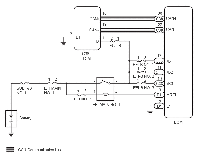
C458219E01
6.115,4.208 6.615,4.625 0.5,0.417 10 false ECM 2.885,1.802 3.344,2 0.458,0.198 10 false C36 2.896,1.969 4.563,2.354 1.667,0.385 10 false TCM 3.146,0.573 3.76,0.771 0.615,0.198 10 false CAN+ 3.135,0.969 3.75,1.167 0.615,0.198 10 false CAN- 2.667,1.219 3.281,1.417 0.615,0.198 10 false E1 5.833,0.563 6.448,0.76 0.615,0.198 10 false CAN+ 5.833,0.948 6.448,1.146 0.615,0.198 10 false CAN- 5.833,2.448 6.448,2.646 0.615,0.198 10 false +B2 5.833,2.854 6.448,3.052 0.615,0.198 10 false +B3 5.844,3.25 6.458,3.448 0.615,0.198 10 false MREL 3.594,0.375 4.208,0.573 0.615,0.198 10 false 18 5.542,0.396 6.156,0.594 0.615,0.198 10 false 28 5.542,0.792 6.156,0.99 0.615,0.198 10 false 27 3.594,0.771 4.208,0.969 0.615,0.198 10 false 19 5.521,1.865 6.135,2.063 0.615,0.198 10 false 12 5.583,3.073 6.198,3.271 0.615,0.198 10 false 3 5.844,3.646 6.458,3.844 0.615,0.198 10 false E1 5.531,2.677 6.146,2.875 0.615,0.198 10 false 10 2.458,1.104 3.073,1.302 0.615,0.198 10 false 2 3.25,3.594 4.479,3.792 1.229,0.198 10 false EFI MAIN NO. 1 0.677,4.063 1.906,4.26 1.229,0.198 10 false Battery 0.563,5.177 4.229,5.375 3.667,0.198 10 false : CAN Communication Line 3.302,1.365 3.917,1.563 0.615,0.198 10 false +B 3.604,1.25 4.219,1.448 0.615,0.198 10 false 1 1.552,3.01 2.177,3.479 0.625,0.469 10 false EFI MAIN NO. 1 3.844,1.521 5.219,1.719 1.375,0.198 10 false ECT-B 3.281,3.125 3.896,3.323 0.615,0.198 10 false 1 3.281,2.729 3.896,2.927 0.615,0.198 10 false 3 4.052,2.729 4.667,2.927 0.615,0.198 10 false 5 4.052,3.125 4.667,3.323 0.615,0.198 10 false 2 5.833,2.063 6.448,2.26 0.615,0.198 10 false +B 5.531,2.281 6.146,2.479 0.615,0.198 10 false 11 5.583,3.469 6.198,3.667 0.615,0.198 10 false 9 5.479,2.854 5.938,3.052 0.458,0.198 10 false C38 5.479,0.583 5.938,0.781 0.458,0.198 10 false C38 5.479,0.979 5.938,1.177 0.458,0.198 10 false C38 5.469,2.458 5.927,2.656 0.458,0.198 10 false C38 5.469,2.063 5.927,2.26 0.458,0.198 10 false C38 5.51,3.25 5.823,3.448 0.313,0.198 10 false B1 5.521,3.646 5.833,3.844 0.313,0.198 10 false B1 2.604,3.396 3.979,3.594 1.375,0.198 10 false EFI NO. 2 2.958,3.104 3.573,3.302 0.615,0.198 10 false 2 2.708,3.115 3.323,3.313 0.615,0.198 10 false 1 0.583,3.01 1.167,3.51 0.583,0.5 10 false SUB R/B NO. 1 1.927,2.698 2.542,2.896 0.615,0.198 10 false 2 1.688,2.698 2.302,2.896 0.615,0.198 10 false 1 4.667,2.188 6.354,2.385 1.688,0.198 10 false EFI-B NO. 1 4.677,2.594 6.365,2.792 1.688,0.198 10 false EFI-B NO. 2 4.677,3 6.365,3.198 1.688,0.198 10 false EFI-B NO. 3 5.063,2.729 5.677,2.927 0.615,0.198 10 false 2 5.063,2.323 5.677,2.521 0.615,0.198 10 false 2 5.052,1.938 5.667,2.135 0.615,0.198 10 false 2 4.823,2.333 5.438,2.531 0.615,0.198 10 false 1 4.813,2.729 5.427,2.927 0.615,0.198 10 false 1 4.823,1.948 5.438,2.146 0.615,0.198 10 false 1 3.885,1.26 4.5,1.458 0.615,0.198 10 false 2 4.115,1.26 4.729,1.458 0.615,0.198 10 false 1

CAUTION / NOTICE / HINT

NOTICE:

Perform registration and/or initialization when parts related to the automatic transmission are replaced.

Click hereDrivetrain>AJA0F (AUTOMATIC TRANSMISSION / TRANSAXLE)>AUTOMATIC TRANSMISSION SYSTEM (for V35A-FTS)>PRECAUTION


PROCEDURE

1.CHECK TERMINAL VOLTAGE (POWER SOURCE OF ECM)
a.

Disconnect the ECM connector.


b.

Turn the ignition switch to ON.


c.

Measure the voltage according to the value(s) in the table below.

Standard Voltage:
Tester Connection Switch Condition Specified Condition

Click Location & Routing(C38,B1)Location & Routing

Click Connector(C38)Engine Compartment>Connecting Wire / Cooling Fan Wire / Engine Wire / Fuel Pump Motor Wire / No. 1 Connecting Wire / No. 10 Engine Wire / No. 2 Connecting Wire / No. 3 Connecting Wire / No. 4 Connecting Wire / Sensor Wire / Turbocharger Wire>ECM

Click Connector(B1)Engine Compartment>Engine Room Main Wire / Lamp Wire / No. 2 Engine Room Wire / No. 2 Lamp Wire / No. 3 Engine Room Wire / No. 6 Engine Room Wire / Washer Wiring Assembly>ECM

C38-12 (+B) - B1-9 (E1) Ignition switch ON 11 to 14 V
C38-11 (+B2) - B1-9 (E1) Ignition switch ON 11 to 14 V
C38-10 (+B3) - B1-9 (E1) Ignition switch ON 11 to 14 V


Result:
Proceed to
OK
NG


OK

2.CHECK HARNESS AND CONNECTOR (TCM - ECM)

NG

GO TO SFI SYSTEM (ECM POWER SOURCE CIRCUIT)

2.CHECK HARNESS AND CONNECTOR (TCM - ECM)
a.

Disconnect the TCM connector.


b.

Disconnect the ECM connector.


c.

Measure the resistance according to the value(s) in the table below.

Standard Resistance:
Tester Connection Condition Specified Condition

Click Location & Routing(C36,C38)Location & Routing

Click Connector(C36)Engine Compartment>Connecting Wire / Cooling Fan Wire / Engine Wire / Fuel Pump Motor Wire / No. 1 Connecting Wire / No. 10 Engine Wire / No. 2 Connecting Wire / No. 3 Connecting Wire / No. 4 Connecting Wire / Sensor Wire / Turbocharger Wire>Transmission Control ECU Assembly

Click Connector(C38)Engine Compartment>Connecting Wire / Cooling Fan Wire / Engine Wire / Fuel Pump Motor Wire / No. 1 Connecting Wire / No. 10 Engine Wire / No. 2 Connecting Wire / No. 3 Connecting Wire / No. 4 Connecting Wire / Sensor Wire / Turbocharger Wire>ECM

C36-18 (CAN+) - C38-28 (CAN+) Always Below 1 Ω
C36-19 (CAN-) - C38-27 (CAN-) Always Below 1 Ω
C36-18 (CAN+) or C38-28 (CAN+) - Body ground Always 10 kΩ or higher
C36-19 (CAN-) or C38-27 (CAN-) - Body ground Always 10 kΩ or higher


Result:
Proceed to
OK
NG


OK

3.REPLACE ECM

NG

REPAIR OR REPLACE HARNESS OR CONNECTOR

3.REPLACE ECM

NEXT

4.CHECK DTC OUTPUT (DTC U010087)
a.

Clear the DTCs.

Powertrain > Transmission > Clear DTCs
50002 373

b.

Turn the ignition switch off and wait for at least 30 seconds.


c.

Read the DTCs.

Powertrain > Transmission > Trouble Codes
50001 373

Result:
Result Proceed to
DTCs are not output A
DTC U010087 is output B


A

END

B

5.REPLACE TCM