BRAKE CONTROL / DYNAMIC CONTROL SYSTEMS ELECTRONICALLY CONTROLLED BRAKE SYSTEM C13807E Stop Lamp Relay Actuator Stuck On
DESCRIPTION
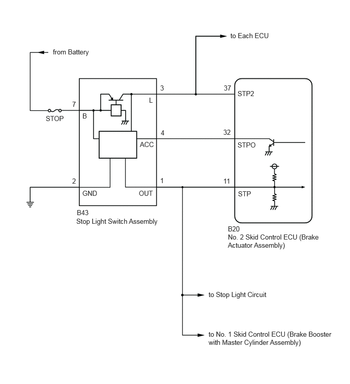
When any of the following conditions are met, the No. 2 skid control ECU (brake actuator assembly) sets the drive output (STPO) ON which operates the stop light control relay (stop light switch assembly) and turns on the stop lights.
Pre-collision brake is operating.
The dynamic radar cruise control system is operating and is applying the brakes.
Secondary collision brake is operating.
Brake hold is operating.
The parking brake is engaged while the vehicle is being driven.
The lane tracing assist system is operating and is applying the brakes.
Trailer sway control brake is operating.
Downhill assist control brake is operating.
Crawl control brake is operating.
Multi-terrain select control brake is operating.
| DTC No. | Detection Item | DTC Detection Condition | Trouble Area | DTC Output from | Note |
|---|---|---|---|---|---|
| C13807E | Stop Lamp Relay Actuator Stuck On | When the IG1 terminal voltage exceeds 10 V and the +BS terminal voltage is 9.5 V or higher, stop light drive output (STPO) is OFF, STP2 is OFF and STP is ON continuously for 5 seconds or more. |
·
Wire harness and connector
·
Stop light switch assembly
·
STP circuit
·
STP2 circuit
·
No. 2 skid control ECU (brake actuator assembly) |
Brake/EPB | Output ECU: No. 2 skid control ECU (brake actuator assembly) |
WIRING DIAGRAM
CAUTION / NOTICE / HINT
- NOTICE:
-
·
Inspect the fuses for circuits related to this system before performing the following procedure.
·After replacing the No. 2 skid control ECU (brake actuator assembly), perform "Calibration".
Click hereBrake>BRAKE CONTROL / DYNAMIC CONTROL SYSTEMS>ELECTRONICALLY CONTROLLED BRAKE SYSTEM>UTILITY
PROCEDURE
Check the DTCs that are output.
- Chassis > Brake/EPB > Trouble Codes
- 50001 435
- Result:
-
Result Proceed to Only C13807E is output A C13807E and other DTCs are output B
A
B
With the brake pedal released, check the illumination status of the stop lights.
- Result:
-
Result Proceed to The stop lights are illuminated. A The stop lights are not illuminated. B
A
B
Make sure that there is no looseness at the locking part and the connecting part of the connectors.
- OK:
-
The connector is securely connected.
Disconnect the B20 No. 2 skid control ECU (brake actuator assembly) connector.
Check both the connector case and the terminals for deformation and corrosion.
- OK:
-
No deformation or corrosion.
Measure the voltage according to the value(s) in the table below.
- Standard Voltage:
-
Tester Connection Condition Specified Condition Click Location & Routing(B20)Location & Routingewd_type=routing;type=c;code=B20
B20-11 (STP) - Body ground Stop light switch assembly off
(Brake pedal released)Below 1.5 V
- Result:
-
Proceed to OK NG
OK
for LHD: Click hereBrake>BRAKE CONTROL / DYNAMIC CONTROL SYSTEMS>BRAKE ACTUATOR (for LHD)>REMOVAL
for RHD: Click hereBrake>BRAKE CONTROL / DYNAMIC CONTROL SYSTEMS>BRAKE ACTUATOR (for RHD)>REMOVAL
NG
Make sure that there is no looseness at the locking part and the connecting part of the connectors.
- OK:
-
The connector is securely connected.
Disconnect the B43 stop light switch assembly connector.
Check both the connector case and the terminals for deformation and corrosion.
- OK:
-
No deformation or corrosion.
Measure the voltage according to the value(s) in the table below.
- Standard Voltage:
-
Tester Connection Condition Specified Condition Click Location & Routing(B20)Location & Routingewd_type=routing;type=c;code=B20
B20-11 (STP) - Body ground Always Below 1.5 V
- Result:
-
Proceed to OK NG
OK
NG
Check that there is no short to +B in the STP circuit (wire harnesses, connectors, stop lights and ECUs).
- OK:
-
No short to +B.
- Result:
-
Proceed to OK NG
OK
Click hereGeneral>INTRODUCTION>HOW TO TROUBLESHOOT ECU CONTROLLED SYSTEMS>HOW TO PROCEED WITH TROUBLESHOOTING
NG
Make sure that there is no looseness at the locking part and the connecting part of the connectors.
- OK:
-
The connector is securely connected.
Disconnect the B20 No. 2 skid control ECU (brake actuator assembly) connector.
Check both the connector case and the terminals for deformation and corrosion.
- OK:
-
No deformation or corrosion.
Measure the voltage according to the value(s) in the table below.
- Standard Voltage:
-
Tester Connection Condition Specified Condition Click Location & Routing(B20)Location & Routingewd_type=routing;type=c;code=B20
B20-37 (STP2) - Body ground Stop light switch assembly on (Brake pedal depressed) 11 to 14 V
- Result:
-
Proceed to OK NG
OK
for LHD: Click hereBrake>BRAKE CONTROL / DYNAMIC CONTROL SYSTEMS>BRAKE ACTUATOR (for LHD)>REMOVAL
for RHD: Click hereBrake>BRAKE CONTROL / DYNAMIC CONTROL SYSTEMS>BRAKE ACTUATOR (for RHD)>REMOVAL
NG
Make sure that there is no looseness at the locking part and the connecting part of the connector.
- OK:
-
The connector is securely connected.
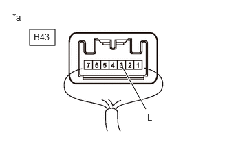
| *a | Component with harness connected (Stop Light Switch Assembly) |
Measure the voltage according to the value(s) in the table below.
- Standard Voltage:
-
Tester Connection Condition Specified Condition Click Location & Routing(B43)Location & Routingewd_type=routing;type=c;code=B43
Click Connector(B43)Instrument Panel>Engine Room Main Wire / Heater Blower Wire>Stop Light Switch Assemblyewd_type=component;type=c;code=B43;pinno=3
B43-3 (L) - Body ground Stop light switch assembly on (Brake pedal depressed) 11 to 14 V
- Result:
-
Proceed to OK NG
OK
NG
Check that there is no short to ground in the STP2 circuit (wire harnesses, connectors and ECUs)
- OK:
-
There is no short to ground.
- Result:
-
Proceed to OK NG
OK
NG