DRIVE SHAFT / PROPELLER SHAFT FRONT DRIVE SHAFT ASSEMBLY REASSEMBLY
CAUTION / NOTICE / HINT
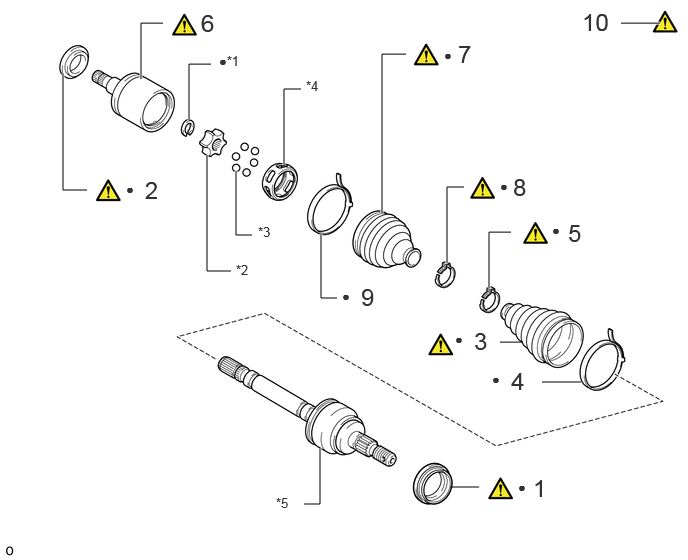
| Procedure | Part Name Code |

|

|

|
|
|---|---|---|---|---|---|
| 1 | FRONT AXLE HUB DUST SEAL LH | 43502K | ( ) |
- | - |
| 2 | FRONT DRIVE SHAFT DUST COVER LH | 41336E | () |
- | - |
| 3 | OUTBOARD JOINT BOOT | - | () |
- | - |
| 4 | FRONT NO. 2 AXLE OUTBOARD JOINT BOOT CLAMP LH | 43447F | - | - | - |
| 5 | FRONT AXLE OUTBOARD JOINT BOOT CLAMP LH | 43447E | () |
- | - |
| 6 | INBOARD JOINT | - | () |
- | - |
| 7 | INBOARD JOINT BOOT | - | () |
- | - |
| 8 | FRONT AXLE INBOARD JOINT BOOT CLAMP LH | 43448F | () |
- | - |
| 9 | FRONT NO. 2 AXLE INBOARD JOINT BOOT CLAMP LH | 43448G | () |
- | - |
| 10 | INSPECT FRONT DRIVE SHAFT ASSEMBLY LH | 43420 | () |
||
| *1 | SNAP RING | *2 | INNER RACE |
| *3 | BALL | *4 | CAGE |
| *5 | FRONT DRIVE OUTBOARD JOINT ASSEMBLY | - | - |
| ● | Non-reusable part | - | - |
CAUTION / NOTICE / HINT
- NOTICE:
-
·
When using a vise, place aluminum plates between the part and vise.
·When using a vise, do not overtighten it.
- HINT:
-
·
Use the same procedure for the RH and LH sides.
·The procedure listed below is for the LH side.
PROCEDURE

 43502K 1.INSTALL FRONT AXLE HUB DUST SEAL LH
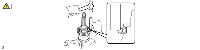
Using a brass bar and hammer, tap on the front drive outboard joint assembly until a new front axle hub dust seal LH contacts the edge of the front drive outboard joint assembly.
- NOTICE:
-
·
Do not damage the front axle hub dust seal LH.
·The front axle hub dust seal LH should be installed completely.
·Make sure to install the front axle hub dust seal LH in the correct direction.
41336E 2.INSTALL FRONT DRIVE SHAFT DUST COVER LH
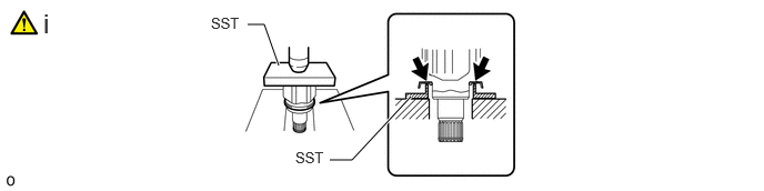
Using SST and a press, press in a new front drive shaft dust cover LH until the inboard joint contacts the edge of the inboard joint.
- SST
-
09527-10011
09316-20011
- NOTICE:
-
·
Do not damage the front drive shaft dust cover LH.
·The front drive shaft dust cover LH should be installed completely.
·Make sure to install the front drive shaft dust cover LH in the correct direction.
3.INSTALL OUTBOARD JOINT BOOT
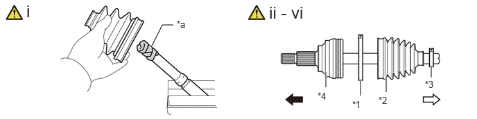
| *1 | Front No. 2 Axle Outboard Joint Boot Clamp LH | *2 | Outboard Joint Boot |
| *3 | Front Axle Outboard Joint Boot Clamp LH | *4 | Front Drive Outboard Joint Assembly |
| *a | Protective Tape | - | - |

|
Outboard Joint Side |

|
Inboard Joint Side |
Before installing the outboard joint boot, wrap the splines of the front drive outboard joint assembly with protective tape to prevent the outboard joint boot from being damaged.
Install new parts to the front drive outboard joint assembly in the following order.
Front No. 2 axle outboard joint boot clamp LH
Outboard joint boot
Front axle outboard joint boot clamp LH
Install the outboard joint boot so that it is between the front No. 2 axle outboard joint boot clamp LH and front drive outboard joint assembly.
Temporarily install the front axle outboard joint boot clamp LH to the outboard joint boot.
Pack the front drive outboard joint assembly and outboard joint boot with grease from the boot kit.
- Standard grease capacity:
-
207.0 to 217.0 g (7.31 to 7.65 oz.)
Install the outboard joint boot to the groove of the front drive outboard joint assembly.
- NOTICE:
-
·
Do not apply grease to the part of the outboard joint boot that contacts the groove.
·Do not allow foreign matter to enter the outboard joint boot.
43447F 4.INSTALL FRONT NO. 2 AXLE OUTBOARD JOINT BOOT CLAMP LH

43447E 5.INSTALL FRONT AXLE OUTBOARD JOINT BOOT CLAMP LH
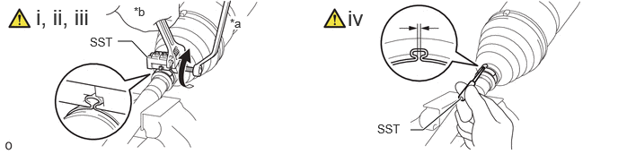
| *a | Turn | *b | Hold |
Install SST to the front axle outboard joint boot clamp LH, and then while pressing the outboard joint boot, slightly tighten the SST bolt.
- SST
-
09521-24010
- NOTICE:
-
·
Correctly set the front axle outboard joint boot clamp LH to the guide groove.
·Do not damage the outboard joint boot.
Tighten SST so that the front axle outboard joint boot clamp LH is pinched.
- Standard clearance:
-
1.5 mm (0.0591 in.) or less
- NOTICE:
-
·
When tightening SST, make sure the clearance of the front axle outboard joint boot clamp LH is within the standard clearance.
·Do not damage the outboard joint boot.
Remove SST from the front axle outboard joint boot clamp LH.
Using SST, measure the clearance of the front axle outboard joint boot clamp LH.
- SST
-
09240-00021
- Standard clearance:
-
1.5 mm (0.0591 in.) or less
- NOTICE:
-
If the measured value exceeds the specified value, retighten the front axle outboard joint boot clamp LH.
6.INSTALL INBOARD JOINT
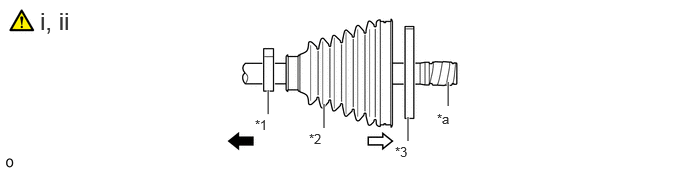
| *1 | Front Axle Inboard Joint Boot Clamp LH | *2 | Inboard Joint Boot |
| *3 | Front No. 2 Axle Inboard Joint Boot Clamp LH | - | - |
| *a | Protective Tape | - | - |
|
|
Outboard Joint Side |
|
Inboard Joint Side |
Install new parts to the front drive outboard joint assembly in the following order.
Front axle inboard joint boot clamp LH
Inboard joint boot
Front No. 2 axle inboard joint boot clamp LH
- HINT:
-
Before installing the front axle inboard joint boot, wrap protective tape around the spline of the outboard joint shaft to prevent damaging the front axle inboard joint boot.
Remove the protective tape from the front drive outboard joint assembly.
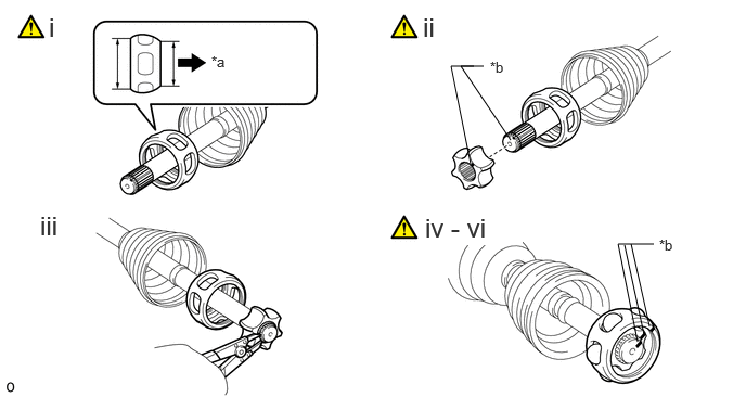
| *a | Outboard Joint Side | *b | Matchmark |
Install the cage to the outboard joint shaft.
- NOTICE:
-
Insert the cage with its smaller inner diameter side facing the outboard joint.
Align the matchmarks and install the inner race to the outboard joint shaft.
Using a snap ring expander, install a new snap ring.
Align the matchmarks placed before removal, and install the cage to the inner race.
Install the 6 balls.
- HINT:
-
Apply grease onto the balls to keep them from falling out.
Pack the front axle inboard joint set LH and front axle inboard joint boot with grease from a boot kit.
- Standard grease capacity:
-
242.0 to 252.0 g (8.54 to 8.88 oz.)
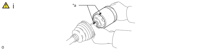
| *a | Matchmark | - | - |
Align the matchmarks placed before removal, and install the inboard joint to the outboard joint shaft.
7.INSTALL INBOARD JOINT BOOT
Install the inboard joint boot to the inboard joint.
- NOTICE:
-
·
Do not apply grease to the part of the inboard joint boot that contacts the groove.
·Do not allow foreign matter to enter the inboard joint boot.
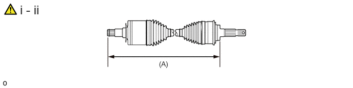
Check that the inboard joint boot and outboard joint boot are not stretched or contracted when the front drive shaft assembly is at the standard length.
- Dimension (A) (w/ Differential Lock):
-
for LH Side 610.27 mm (2.00 ft.) for RH Side 658.27 mm (2.16 ft.)
- Dimension (A) (w/o Differential Lock):
-
for LH Side 589.17 mm (1.93 ft.) for RH Side 637.17 mm (2.09 ft.)
- NOTICE:
-
Keep the front drive shaft assembly level during inspection.
If the inboard joint boot and outboard joint boot are stretched or contracted, correct them.
43448F 8.INSTALL FRONT AXLE INBOARD JOINT BOOT CLAMP LH
|
|
|
43448G 9.INSTALL FRONT NO. 2 AXLE INBOARD JOINT BOOT CLAMP LH
Use the same procedure described for the front No. 2 axle outboard joint boot clamp LH.
43420 10.INSPECT FRONT DRIVE SHAFT ASSEMBLY LH