RM38G0E _51 Engine / Hybrid System _101531 1GR-FE EMISSION CONTROL _0474433 AIR SWITCHING VALVE(for Bank 2) A
1GR-FE EMISSION CONTROL AIR SWITCHING VALVE(for Bank 2) INSTALLATION
CAUTION / NOTICE / HINT
COMPONENTS (INSTALLATION)
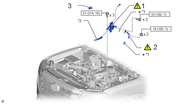
2.969,0.396 3.719,0.563 0.75,0.167 5.458,0.438 6.208,0.604 0.75,0.167 5.51,0.979 6.26,1.146 0.75,0.167 2.844,0.198 3.01,0.198 3.01,0.198 3.302,0.281 true 4.698,1.271 5.01,1.75 5.01,1.75 5.177,1.75 true 4.375,1.063 4.813,0.438 4.813,0.438 4.979,0.438 true 4.542,1.573 4.958,1.99 4.958,1.99 5.125,1.99 true 3.042,0.75 3.208,0.75 3.208,0.75 3.542,1.448 true 4.083,0.948 4.74,0.198 4.74,0.198 4.906,0.198 true 3.719,0.479 3.885,0.479 false 5.125,0.688 5.125,0.521 5.125,0.521 5.458,0.521 false 5.177,1.229 5.177,1.063 5.177,1.063 5.51,1.063 false 5.615,1.573 6.177,1.917 0.563,0.344 18 false 2 5.063,0.344 5.438,0.51 0.375,0.167 10 false ● *1 5.208,1.906 5.583,2.073 0.375,0.167 10 false ● *1 2.479,0.063 3.031,0.438 0.552,0.375 18 false 3 2.844,0.677 3.219,0.844 0.375,0.167 10 false *2 5.219,0.625 5.677,0.823 0.458,0.198 10 false x 2 5.25,1.167 5.708,1.365 0.458,0.198 10 false x 2 4,0.469 4.458,0.667 0.458,0.198 10 false x 3 5.167,0.063 5.729,0.406 0.563,0.344 18 false 1 3.031,0.406 3.781,0.573 0.75,0.167 8 false 21 (214, 15) 5.521,0.458 6.271,0.625 0.75,0.167 8 false 10 (102, 7) 5.583,0.99 6.333,1.156 0.75,0.167 8 false 10 (102, 7)
| Procedure | Part Name Code |

|

|

|
|
|---|---|---|---|---|---|
| 1 | NO. 2 EMISSION CONTROL VALVE SET | 25702B | ( ) |
- | - |
| 2 | NO. 2 AIR TUBE | 17362 | () |
- | - |
| 3 | NO. 1 VACUUM SWITCHING VALVE ASSEMBLY | 25860 | - | - | - |
| *1 | NO. 2 AIR TUBE GASKET | *2 | AIR TUBE ASSEMBLY |

|
N*m (kgf*cm, ft.*lbf): Specified torque | ● | Non-reusable part |
PROCEDURE

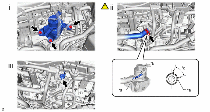
 25702B 1.INSTALL NO. 2 EMISSION CONTROL VALVE SET
a.
5.99,2.563 6.26,3.052 6.26,3.052 6.344,3.052 true 4.229,3.063 4.313,3.063 4.313,3.063 4.542,2.677 true 4.708,2.604 5.021,2.146 5.021,2.146 5.104,2.146 true 5.135,2.073 5.302,2.24 0.167,0.167 10 true *b 6.385,2.979 6.552,3.146 0.167,0.167 10 false *a 4.042,2.979 4.208,3.146 0.167,0.167 10 false *a 6.198,2.229 6.365,2.396 0.167,0.167 10 false *c 0.292,0.094 0.573,0.448 0.281,0.354 18 false i 3.76,0.094 4.042,0.448 0.281,0.354 18 false ii 0.281,2.073 0.563,2.427 0.281,0.354 18 false iii
| *a | Paint Mark | *b | Sensing Hose |
| *c | 60° | - | - |
i.
Install the No. 2 emission control valve set with 3 bolts.
- Torque:
- 21 N*m (214 kgf*cm, 15 ft.*lbf)
ii.
Connect the air tube assembly and slide the hose clip to secure it.
- NOTICE:
-
·
Align the paint mark of air tube assembly with sensing hose.
·Align the hose and the hose clip at the locations shown in the illustration and install them.
iii.
Connect the connector.
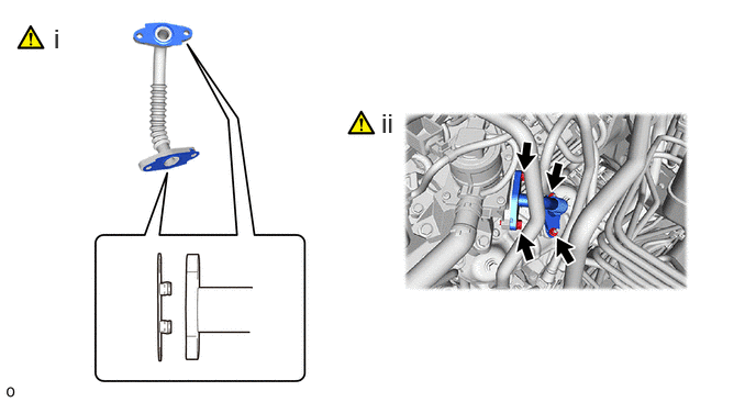
17362 2.INSTALL NO. 2 AIR TUBE
a.
0.51,0.219 0.792,0.573 0.281,0.354 18 false i 3.615,1.021 3.896,1.375 0.281,0.354 18 false ii
i.
Install 2 new No. 2 air tube gaskets to the No. 2 air tube as shown in the illustration.
ii.
Install the No. 2 air tube with the 2 bolts and 2 nuts.
- Torque:
- 10 N*m (102 kgf*cm, 7 ft.*lbf)
- NOTICE:
-
Be careful not to damage the installation surface of the gaskets.
25860 3.INSTALL PURGE VSV (NO. 1 VACUUM SWITCHING VALVE ASSEMBLY)