Home › Drivetrain › AJA0F (AUTOMATIC TRANSMISSION / TRANSAXLE) › AUTOMATIC TRANSMISSION UNIT (for F33A-FTV) › from 2021.07
RM38G0E _52 Drivetrain _100435 AJA0F AUTOMATIC TRANSMISSION / TRANSAXLE _0484532 AUTOMATIC TRANSMISSION UNIT(for F33A-FTV) A

AJA0F AUTOMATIC TRANSMISSION / TRANSAXLE  AUTOMATIC TRANSMISSION UNIT(for F33A-FTV)  DISASSEMBLY  


CAUTION / NOTICE / HINT
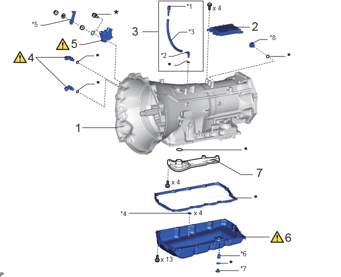
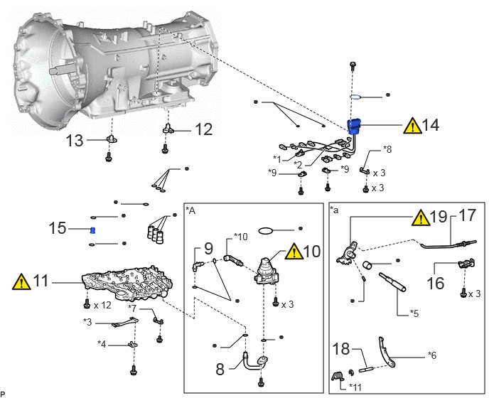
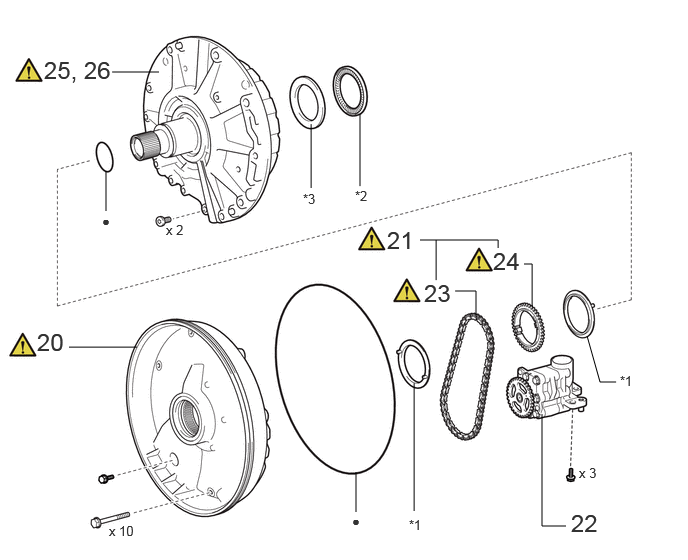
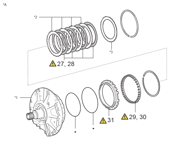
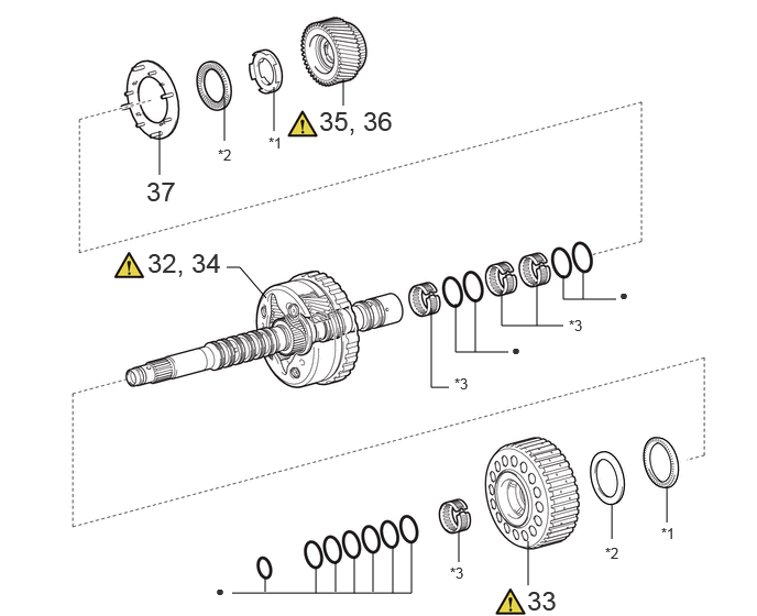
COMPONENTS (DISASSEMBLY)
C460368C01
3.333,0.021 4.271,1.5 0.938,1.479 4.479,3.344 5.063,3.677 5.063,3.677 5.313,3.677 false 2.99,0.667 3.323,0.667 false 3.833,3.156 5.083,3.156 false 3.563,0.135 3.896,0.135 false 3.542,1.188 3.625,1.188 3.625,1.188 3.969,1.083 false 3.656,1.375 3.74,1.375 3.74,1.375 3.938,1.271 false 3.604,0.844 3.771,0.677 3.771,0.677 3.938,0.677 false 1.667,0.938 1.75,0.938 1.75,0.938 2.167,0.844 false 0.854,0.531 0.938,0.531 0.938,0.531 1.479,0.406 false 4.958,4.167 5.292,4.167 false 5.083,4.99 5.667,4.99 false 4.625,5.542 4.792,5.542 false 2.708,4.49 3.958,4.49 false 1.729,2.688 2.479,2.688 false 1.99,0.302 2.333,0.302 false 4.625,5.385 5.042,5.385 false 4.604,5.698 5.021,5.698 false 4.917,0.573 5.25,0.573 false 5.667,1.188 6,1.188 false 5.292,0.917 5.458,0.833 5.458,0.833 5.625,0.833 false 1.427,1.865 0.75,1.208 0.75,1.208 1.417,1.208 false 1.635,1.302 1.813,1.177 1.813,1.177 1.979,1.177 false 1.646,1.896 1.823,1.771 1.823,1.771 1.99,1.771 false 1.573,2.542 1.854,2.896 0.281,0.354 18 false 1 3.917,0.052 4.229,0.25 0.313,0.198 10 false *1 3.375,1.083 3.688,1.281 0.313,0.198 10 false *2 3.521,1.25 3.833,1.448 0.313,0.198 10 false ● 3.958,0.583 4.271,0.781 0.313,0.198 10 false *3 5.292,0.406 5.573,0.76 0.281,0.354 18 false 2 2.771,0.51 3.052,0.865 0.281,0.354 18 false 3 0.583,1.063 0.865,1.417 0.281,0.354 18 false 4 1.49,0.771 1.771,1.125 0.281,0.354 18 false 5 0.667,0.427 0.979,0.625 0.313,0.198 10 false *5 2.531,4.417 2.844,4.615 0.313,0.198 10 false *4 5.125,3.031 5.438,3.229 0.313,0.198 10 false ● 3.604,3.75 3.917,3.948 0.313,0.198 10 false x 4 5.333,4.042 5.813,4.354 0.479,0.313 10 false ● 5.99,4.854 6.271,5.208 0.281,0.354 18 false 6 4.469,0.083 4.927,0.281 0.458,0.198 10 false x 4 4.073,4.396 4.531,4.594 0.458,0.198 10 false x 4 5.385,3.49 5.667,3.844 0.281,0.354 18 false 7 4.813,5.417 5.125,5.615 0.313,0.198 10 false ● 3.375,5.375 3.833,5.573 0.458,0.198 10 false x 13 2.375,0.167 2.604,0.427 0.229,0.26 10 false ★ 5.052,5.26 5.365,5.458 0.313,0.198 10 false *6 5.052,5.573 5.365,5.771 0.313,0.198 10 false *7 6.031,1.052 6.51,1.365 0.479,0.313 10 false ● 5.667,0.708 5.979,0.906 0.313,0.198 10 false *8 2.01,1.063 2.49,1.375 0.479,0.313 10 false ● 2.021,1.635 2.5,1.948 0.479,0.313 10 false ●

Procedure Part Name Code
Z101186

Z101188

Z101187

1 SECURE AUTOMATIC TRANSMISSION ASSEMBLY - - - -
2 TCM 89530C - - -
3 BREATHER PLUG SUB-ASSEMBLY - - - -
4 OIL COOLER TUBE UNION - (Click here) - -
5 PARK/NEUTRAL POSITION SWITCH ASSEMBLY 84540 (Click here) - -
6 AUTOMATIC TRANSMISSION OIL PAN SUB-ASSEMBLY 35106 (Click here) - -
7 VALVE BODY OIL STRAINER ASSEMBLY 35330 - - -

*1 NO. 1 BREATHER PLUG (ATM) *2 NO. 2 BREATHER PLUG (ATM)
*3 BREATHER PLUG HOSE *4 TRANSMISSION OIL CLEANER MAGNET
*5 TRANSMISSION CONTROL SHAFT LEVER RH *6 NO. 1 TRANSMISSION OIL FILLER TUBE
*7 OVERFLOW PLUG *8 REFILL PLUG
● Non-reusable part ★ Precoated part

C460369C01
2.698,2.979 4.74,5.76 2.042,2.781 4.823,2.969 7.104,5.771 2.281,2.802 1,3.354 1.333,3.354 false 1.396,3.177 1.729,3.177 false 1.396,3.573 1.729,3.573 false 0.76,4.146 1.25,4.146 false 1.271,2.052 1.604,2.052 false 2.469,1.917 2.802,1.917 false 5.271,1.427 5.604,1.427 false 5.25,1.833 5.896,1.833 false 3.229,5.094 3.365,5.094 3.365,5.094 3.583,4.896 false 5.406,3.865 5.74,3.865 false 6.688,3.167 6.604,3.167 6.604,3.167 6.604,3.604 false 6.365,4.021 6.365,3.854 6.365,3.854 6.698,3.854 false 3.917,3.854 4.104,3.677 4.104,3.677 4.188,3.677 false 2.188,3.302 2.417,3.167 2.417,3.167 2.5,3.167 false 3.354,5.406 3.438,5.406 3.438,5.406 3.583,5.24 false 2.302,3.354 2.417,3.167 false 2.333,3.427 2.448,3.167 false 2.26,2.698 2.479,2.479 2.479,2.479 2.646,2.479 false 2.323,2.729 2.479,2.5 false 2.375,2.771 2.479,2.49 false 5.156,5.115 5.292,5.115 5.292,5.115 5.375,5.385 false 4.406,2.229 4.219,2.354 4.219,2.354 4.135,2.354 false 3.865,4.979 4.031,4.979 false 3.979,3.375 4.313,3.375 false 2.854,3.885 2.854,3.635 2.854,3.635 2.938,3.635 false 5.25,4.417 5.333,4.417 5.333,4.417 5.333,4.083 false 1.396,4.74 1.729,4.74 false 1.583,5.063 1.917,5.063 false 5.135,3.594 5.135,3.177 5.135,3.177 6.052,3.177 false 5.823,4.219 5.823,4.625 5.823,4.625 5.99,4.625 false 5.698,5.24 6.229,5.24 false 2.042,4.531 2.229,4.531 2.229,4.531 2.313,4.719 false 4.083,2.552 4.417,2.552 false 4.792,2.5 4.958,2.5 false 5.323,2.479 5.417,2.208 5.417,2.208 5.583,2.208 false 1.771,2.99 2.104,2.99 false 3.833,1.5 4,1.5 4,1.5 4.75,1.833 false 4.771,2.177 4.552,2.427 4.552,2.427 4.469,2.427 true 2.865,4.198 3.385,4.406 3.385,4.406 3.125,3.823 false 3.323,3.75 3.323,3.5 3.323,3.5 3.406,3.5 false 4,1.5 4.344,1.833 false 4.99,5.542 4.99,5.708 4.99,5.708 5.073,5.708 false 1.771,3.063 1.927,3.281 0.156,0.219 10 false ● 1.781,3.469 1.938,3.667 0.156,0.198 10 false ● 0.698,3.188 1.25,3.542 0.552,0.354 18 false 15 1.375,4.385 1.99,4.583 0.615,0.198 10 false x 12 0.469,3.958 1.021,4.313 0.552,0.354 18 false 11 2.844,1.74 3.396,2.094 0.552,0.354 18 false 12 0.948,1.906 1.5,2.26 0.552,0.354 18 false 13 3.708,1.396 4.01,1.656 0.302,0.26 10 false ● 5.646,1.292 5.854,1.542 0.208,0.25 10 false ● 6.167,1.677 6.719,2.031 0.552,0.354 18 false 14 5.469,2.448 5.927,2.646 0.458,0.198 10 false x 3 5.448,2.667 5.906,2.865 0.458,0.198 10 false x 3 4.365,3.25 4.573,3.5 0.208,0.25 10 false ● 5.792,3.719 6,3.969 0.208,0.25 10 false ● 6.708,3 7.135,3.313 0.427,0.313 18 false 17 6.865,4.219 7.135,4.479 0.271,0.26 10 false x 3 6.24,4 6.792,4.354 0.552,0.354 18 false 16 4.427,3.531 4.979,3.885 0.552,0.354 18 false 10 3.156,5.26 3.708,5.615 0.552,0.354 18 false 8 2.521,3.052 2.729,3.302 0.208,0.25 10 false ● 2.698,2.375 2.906,2.625 0.208,0.25 10 false ● 4.854,4.958 5.406,5.313 0.552,0.354 18 false 18 4.083,4.844 4.292,5.094 0.208,0.25 10 false ● 3.104,4.969 3.313,5.219 0.208,0.25 10 false ● 4.125,4.375 4.583,4.573 0.458,0.198 10 false x 3 2.99,3.49 3.542,3.844 0.552,0.354 18 false 9 5.125,4.313 5.333,4.563 0.208,0.25 10 false ● 2.719,3 3.031,3.198 0.313,0.198 10 false *A 1.219,4.635 1.531,4.833 0.313,0.198 10 false *3 1.427,4.958 1.74,5.156 0.313,0.198 10 false *4 6.281,3.021 6.833,3.375 0.552,0.354 18 false 19 6.01,4.51 6.323,4.708 0.313,0.198 10 false *5 6.271,5.125 6.583,5.323 0.313,0.198 10 false *6 1.875,4.438 2.188,4.635 0.313,0.198 10 false *7 4,2.25 4.313,2.448 0.313,0.198 10 false *1 3.927,2.448 4.24,2.646 0.313,0.198 10 false *9 4.99,2.396 5.302,2.594 0.313,0.198 10 false *9 5.615,2.104 5.927,2.302 0.313,0.198 10 false *8 1.656,2.865 1.865,3.115 0.208,0.25 10 false ● 4.302,2.333 4.615,2.531 0.313,0.198 10 false *2 3.438,4.313 3.74,4.573 0.302,0.26 10 false ● 3.427,3.385 3.74,3.583 0.313,0.198 10 false *10 5.115,5.594 5.427,5.792 0.313,0.198 10 false *11 4.833,2.99 5.146,3.188 0.313,0.198 10 false *a

Procedure Part Name Code
Z101186

Z101188

Z101187

8 NO. 2 TRANSMISSION OIL PIPE 33129G - - -
9 NO. 3 TRANSMISSION OIL PIPE 33129H - - -
10 OIL PUMP WITH MOTOR ASSEMBLY 35300D (Click here) - -
11 TRANSMISSION VALVE BODY ASSEMBLY 35400A (Click here) - -
12 TRANSMISSION REVOLUTION SENSOR (SP2) 89413V - - -
13 TRANSMISSION REVOLUTION SENSOR (NT) 89413N - - -
14 TRANSMISSION WIRE 82125J (Click here) - -
15 TRANSMISSION OIL PIPE 33129F - - -
16 PARKING LOCK PAWL BRACKET 35595 - - -
17 PARKING LOCK ROD SUB-ASSEMBLY 35501 - - -
18 PARKING LOCK PAWL SHAFT 35556 - - -
19 MANUAL VALVE LEVER SUB-ASSEMBLY 35505 (Click here) - -

*A w/ Stop and Start System - -
*1 NO. 1 ATF TEMPERATURE SENSOR *2 NO. 2 ATF TEMPERATURE SENSOR
*3 MANUAL DETENT SPRING SUB-ASSEMBLY *4 MANUAL DETENT SPRING COVER
*5 MANUAL VALVE LEVER SHAFT *6 PARKING LOCK PAWL
*7 WIRE HARNESS CLAMP *8 TRANSMISSION WIRE CLAMP
*9 LOCK PLATE *10 NO. 4 TRANSMISSION OIL PIPE
*11 SPRING - -
*a Parts related to the parking lock - -
● Non-reusable part - -

C459135C01
3.708,5.333 3.708,4.917 false 0.719,3.615 1.427,3.615 false 5.646,4.313 5.646,5.479 5.646,5.479 5.896,5.479 false 4.313,5.323 4.313,3.99 false 6.115,3.5 6.25,3.979 6.25,3.979 6.417,3.979 false 3.75,1.938 3.75,1.188 false 3.24,1.958 3.24,1.292 false 1.167,0.75 1.656,0.75 false 5.542,3.198 5.542,2.75 5.542,2.75 5.458,2.75 false 4.958,3.281 4.958,3.031 4.958,3.031 4.74,3.031 false 5.188,2.583 5.188,2.5 5.188,2.5 4.375,2.5 false 4.542,2.5 4.542,2.917 false 1.104,2.198 1.104,1.781 false 1.135,5.448 1.75,5.646 0.615,0.198 10 false x 10 3.667,5.344 3.823,5.542 0.156,0.198 10 false ● 0.385,3.417 0.938,3.771 0.552,0.354 18 false 20 5.948,5.302 6.5,5.656 0.552,0.354 18 false 22 4.26,5.385 4.573,5.583 0.313,0.198 10 false *1 6.458,3.885 6.771,4.083 0.313,0.198 10 false *1 3.698,1.958 4.01,2.156 0.313,0.198 10 false *2 3.156,1.99 3.469,2.188 0.313,0.198 10 false *3 4.417,2.906 4.823,3.25 0.406,0.344 18 false 23 4.031,2.354 4.583,2.708 0.552,0.354 18 false 21 0.458,0.583 1.427,0.958 0.969,0.375 18 false 25, 26 5.135,2.573 5.542,2.917 0.406,0.344 18 false 24 1.729,2.313 2.344,2.51 0.615,0.198 10 false x 2 6.031,4.844 6.646,5.042 0.615,0.198 10 false x 3 1.063,2.219 1.219,2.417 0.156,0.198 10 false ●

Procedure Part Name Code
Z101186

Z101188

Z101187

20 NO. 2 FRONT OIL PUMP COVER SUB-ASSEMBLY 35308K (Click here) - -
21 DRIVE SPROCKET AND TRANSMISSION DRIVE CHAIN - (Click here) - -
22 OIL PUMP ASSEMBLY WITH DRIVEN SPROCKET - - - -
23 INSPECT TRANSMISSION DRIVE CHAIN 35781C (Click here) - -
24 INSPECT DRIVE SPROCKET 35782 (Click here) - -
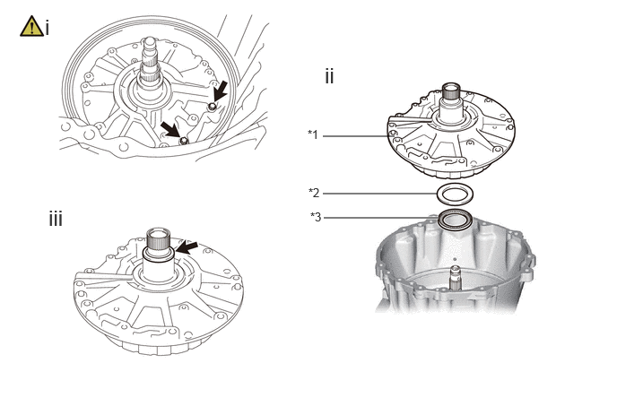
25 REMOVE STATOR SHAFT ASSEMBLY 35370 (Click here) - -
26 INSPECT STATOR SHAFT ASSEMBLY 35370 (Click here) - -

*1 GEAR THRUST WASHER *2 THRUST NEEDLE ROLLER BEARING
*3 THRUST BEARING RACE - -
● Non-reusable part - -

C456980C01
3.031,5.167 3.031,4.667 false 3.75,5.031 3.75,4.531 false 2.583,2.333 3.75,2.333 3.75,2.333 3.75,1.833 false 2.583,2.417 2.583,2.167 false 3.333,2.323 3.333,1.927 false 2.906,2.333 2.906,2.083 false 4.385,4.667 4.385,4.333 false 5.448,4.521 5.448,4.104 false 0.802,3.927 1.24,3.927 false 1.573,0.688 3.26,0.688 3.26,0.688 3.26,0.938 false 2.875,1.083 2.875,0.688 false 2.49,1.135 2.49,0.688 false 2.083,1.24 2.083,0.698 false 4.49,2 4.49,1.677 false 0.115,0.104 0.427,0.302 0.313,0.198 10 false *A 2.99,5.208 3.146,5.406 0.156,0.198 10 false ● 3.719,5.073 3.875,5.271 0.156,0.198 10 false ● 2.302,2.417 3.104,2.771 0.802,0.354 18 false 27, 28 4.323,4.677 4.75,5.031 0.427,0.354 18 false 31 5.198,4.552 6.042,4.865 0.844,0.313 18 false 29, 30 0.583,3.844 0.802,4.073 0.219,0.229 10 false *1 1.365,0.604 1.583,0.833 0.219,0.229 10 false *2 4.406,2.01 4.625,2.24 0.219,0.229 10 false *3

Procedure Part Name Code
Z101186

Z101188

Z101187

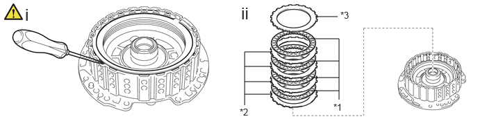
27 REMOVE NO. 1 BRAKE DISC 35681A (Click here) - -
28 INSPECT NO. 1 BRAKE DISC 35681A (Click here) - -
29 REMOVE BRAKE PISTON RETURN SPRING SUB-ASSEMBLY (NO. 1 BRAKE) 35608J (Click here) - -
30 INSPECT BRAKE PISTON RETURN SPRING SUB-ASSEMBLY (NO. 1 BRAKE) 35608J (Click here) - -
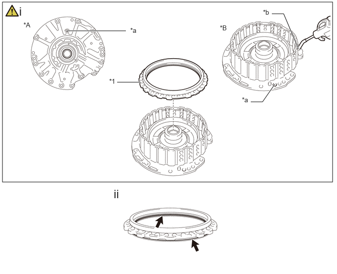
31 NO. 1 BRAKE PISTON 35621 (Click here) - -

*A STATOR SHAFT ASSEMBLY - -
*1 FRONT SUPPORT SUB-ASSEMBLY *2 NO. 1 BRAKE PLATE
*3 NO. 1 BRAKE FLANGE - -
● Non-reusable part - -

C456981C01
3.25,1 3.25,0.75 false 2.594,1.24 2.594,0.823 false 2.125,1.333 2.125,0.917 false 1.51,1.656 1.51,1.24 false 5.833,2.833 5.333,2.833 5.333,2.833 5.333,2.604 false 5.521,2.833 5.521,2.583 false 5.333,3.083 4.75,3.083 4.75,3.083 4.75,2.75 false 5.083,3.083 5.083,2.667 false 4.813,3.333 4.313,3.333 4.313,3.333 4.313,2.875 false 4.5,3.333 4.5,2.833 false 4.25,3.667 4.083,3.667 4.083,3.667 4.083,2.917 false 2.146,2.531 2.271,2.531 2.271,2.531 2.521,2.823 false 4.344,5.323 4.344,5.031 false 2.198,5.615 3.896,5.615 3.896,5.615 3.896,5.135 false 2.51,5.604 2.51,5.479 false 6.313,4.948 6.313,4.615 false 5.792,5.104 5.792,4.771 false 5,5.542 5,5.125 false 2.99,5.615 2.99,5.365 false 3.177,5.604 3.177,5.323 false 3.354,5.615 3.354,5.271 false 3.531,5.604 3.531,5.24 false 3.719,5.615 3.719,5.177 false 4.844,3.229 5,3.427 0.156,0.198 10 false ● 5.865,2.708 6.021,2.906 0.156,0.198 10 false ● 4.99,5.542 5.333,5.823 0.344,0.281 18 false 33 1.385,1.667 1.75,2.021 0.365,0.354 18 false 37 1.396,2.344 2.333,2.813 0.938,0.469 18 false 32, 34 2.542,1.271 2.854,1.469 0.313,0.198 10 false *1 2.063,1.385 2.375,1.583 0.313,0.198 10 false *2 4.302,3.552 4.615,3.75 0.313,0.198 10 false *3 2.042,5.51 2.198,5.708 0.156,0.198 10 false ● 4.26,5.344 4.49,5.583 0.229,0.24 10 false *3 5.385,3 5.698,3.198 0.313,0.198 10 false *3 5.729,5.156 5.979,5.385 0.25,0.229 10 false *2 6.26,4.969 6.49,5.188 0.229,0.219 10 false *1 3.021,1 3.896,1.354 0.875,0.354 18 false 35, 36

Procedure Part Name Code
Z101186

Z101188

Z101187

32 REMOVE FRONT PLANETARY GEAR ASSEMBLY 35720 - - -
33 PLANETARY SUN GEAR ASSEMBLY 35710G (Click here) - -
34 INSPECT FRONT PLANETARY GEAR ASSEMBLY 35720 (Click here) - -
35 REMOVE FRONT PLANETARY SUN GEAR SUB-ASSEMBLY 35706P - - -
36 INSPECT FRONT PLANETARY SUN GEAR SUB-ASSEMBLY 35706P (Click here) - -
37 FRONT PLANETARY OIL RECEIVER 35753B - - -

*1 THRUST BEARING RACE *2 THRUST NEEDLE ROLLER BEARING
*3 NEEDLE ROLLER BEARING - -
● Non-reusable part - -

C456986C01
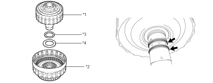
0.104,0.51 7.115,3.115 7.01,2.604 4,0.51 4,0.26 4,0.26 4.25,0.26 false 0.927,1.323 1.063,1.323 1.063,1.323 1.354,2.031 false 1.438,5.375 1.615,5.635 1.615,5.635 1.792,5.635 false 4.417,5.083 4.417,4.5 false 4.406,5 3.083,5 3.083,5 3.083,4.917 false 3.417,5 3.417,4.75 false 3.802,5 3.802,4.667 false 6.229,5.01 6.229,4.115 false 4.927,1.854 4.927,1.552 false 5.229,1.833 5.229,1.469 false 6.542,1.479 6.542,1.104 false 6.875,1.406 6.875,1.031 false 5.688,4.417 5.688,4.135 false 6.844,4.323 6.844,3.917 false 3.677,2.396 3.677,2.146 false 3.708,4 3.708,3.667 false 4.417,3.833 4.417,3.667 4.417,3.667 2.667,3.667 false 3.417,3.667 3.417,4.083 false 3.083,3.667 3.083,4.167 false 1.781,1.083 1.917,1.083 1.917,1.083 2.208,1.792 false 2.792,2.448 2.792,2.146 false 3.167,2.365 3.167,2.063 false 5.76,2 5.76,1.667 false 4.625,2.167 4.625,1.583 false 4.385,2.26 4.385,1.677 false 4.125,5 4.125,4.583 false 4.083,3.917 4.083,3.667 false 2.875,4.958 2.875,5.458 false 4.281,0.104 4.688,0.448 0.406,0.344 18 false 38 0.573,1.135 0.938,1.479 0.365,0.344 18 false 39 1.448,0.927 1.813,1.323 0.365,0.396 18 false 42 1.844,5.448 2.302,5.771 0.458,0.323 18 false 43 4.354,5.104 5.365,5.458 1.01,0.354 18 false 44, 45 5.563,4.427 5.948,4.76 0.385,0.333 18 false 47 2.729,2.458 2.927,2.719 0.198,0.26 10 false *1 6.469,1.479 6.698,1.74 0.229,0.26 10 false *2 6.813,4.406 6.979,4.625 0.167,0.219 10 false ● 4.344,2.24 4.5,2.438 0.156,0.198 10 false ● 5.781,1.979 6.146,2.375 0.365,0.396 18 false 41 2.5,3.552 2.813,3.854 0.313,0.302 10 false *3 3.094,2.385 3.292,2.646 0.198,0.26 10 false *2 3.563,2.396 3.927,2.792 0.365,0.396 18 false 40 4.583,2.188 4.74,2.385 0.156,0.198 10 false ● 2.813,5.469 3.125,5.771 0.313,0.302 10 false *4 5.156,1.844 5.354,2.104 0.198,0.26 10 false *2 4.865,1.865 5.063,2.125 0.198,0.26 10 false *1 6.813,1.427 7.01,1.688 0.198,0.26 10 false *1 6.094,5.01 6.479,5.344 0.385,0.333 18 false 46

Procedure Part Name Code
Z101186

Z101188

Z101187

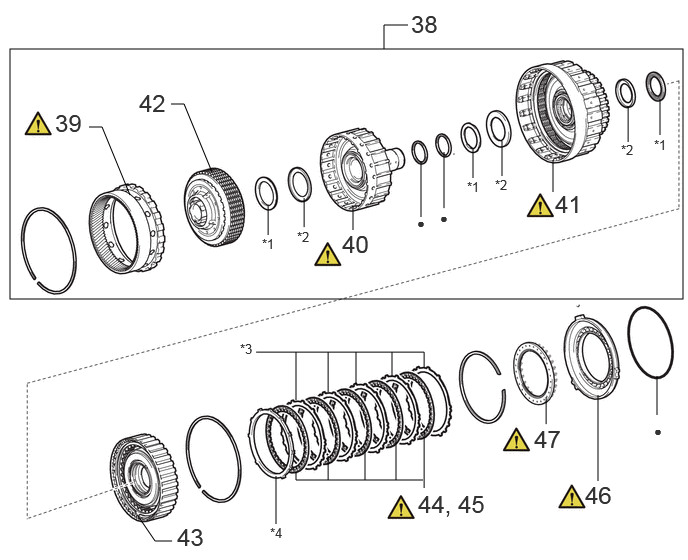
38 FRONT PLANETARY RING GEAR WITH C-1 CLUTCH ASSEMBLY 35743 - - -
39 FRONT PLANETARY RING GEAR 35743 (Click here) - -
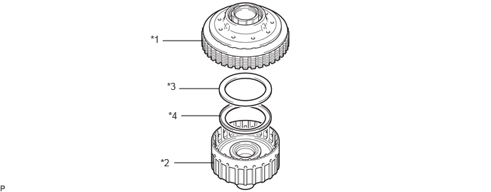
40 C-2 DRUM SUB-ASSEMBLY 3560B - - -
41 INSPECT C-1 CLUTCH ASSEMBLY 35610 (Click here) - -
42 C-2 CLUTCH ASSEMBLY 35650L - - -
43 C-3 CLUTCH ASSEMBLY 35640 - - -
44 REMOVE NO. 2 BRAKE DISC 35682A (Click here) - -
45 INSPECT NO. 2 BRAKE DISC 35682A (Click here) - -
46 NO. 2 BRAKE PISTON 35622G (Click here) - -
47 INSPECT BRAKE PISTON RETURN SPRING SUB-ASSEMBLY (NO. 2 BRAKE) 35608J (Click here) - -

*1 THRUST NEEDLE ROLLER BEARING *2 THRUST BEARING RACE
*3 NO. 2 BRAKE PLATE *4 NO. 2 BRAKE FLANGE
● Non-reusable part - -

C468572C01
0.156,3.594 3.667,5.771 3.51,2.177 3.948,3.26 6.333,5.167 2.385,1.906 3.406,0.354 5.604,2.354 2.198,2 3.677,5.646 4.24,5.646 false 1.24,4.531 1.24,4.365 1.24,4.365 0.354,4.365 false 0.49,4.667 0.49,4.365 false 1.99,4.135 2.24,4.135 2.24,4.135 2.438,4.375 false 2.802,5.323 2.802,5.063 2.802,5.063 2.927,4.927 false 5.167,4.802 5.167,4.49 false 5.833,4.792 5.833,4.292 false 0.417,2.188 0.417,0.604 0.417,0.604 0.667,0.604 false 0.969,1.667 0.969,1.073 0.969,1.073 1.156,1.073 false 1.823,2.042 1.813,2.479 1.813,2.479 2.01,2.479 false 2.479,0.49 2.708,0.49 2.708,0.49 2.865,1.313 false 3.323,1.604 3.25,2.167 3.25,2.167 3.083,2.167 false 5.833,5.406 5.833,5.177 false 3.24,0.552 3.406,0.552 false 6.656,1.313 6.656,1.063 false 0.188,2.24 0.188,0.24 0.188,0.24 0.438,0.24 false 3.521,1.844 3.521,1.594 false 2.042,5.438 2.042,5.271 false 4.917,1.698 4.917,1.479 false 4.25,1.865 4.25,1.677 false 5.708,1.24 5.708,0.99 false 5.927,1.156 5.927,0.906 false 3.698,2.052 3.698,1.552 false 4.531,5.49 4.938,5.792 0.406,0.302 18 false 48 3.427,5.25 3.719,5.458 0.292,0.208 10 false x 2 0.24,4.26 0.469,4.552 0.229,0.292 10 false ● 1.875,4.021 2.063,4.25 0.188,0.229 10 false ● 5.781,4.813 6.01,5.073 0.229,0.26 10 false *1 4.177,1.885 4.385,2.146 0.208,0.26 10 false *2 1.438,0.99 2.313,1.302 0.875,0.313 18 false 53, 54 2.26,2.375 3.063,2.719 0.802,0.344 18 false 55, 56 2.979,2.052 3.24,2.333 0.26,0.281 10 false ● 5.042,4.813 5.406,5.125 0.365,0.313 18 false 52 5.698,5.438 6.063,5.75 0.365,0.313 18 false 51 4.781,1.719 5.354,2.292 0.573,0.573 18 false 59 1.927,5.448 2.292,5.76 0.365,0.313 18 false 49 3.458,1.854 3.688,2.115 0.229,0.26 10 false *3 0.458,0.146 0.688,0.406 0.229,0.26 10 false *3 2.906,0.385 3.479,0.958 0.573,0.573 18 false 58 2.833,5.292 3.24,5.594 0.406,0.302 18 false 50 5.635,1.25 5.865,1.51 0.229,0.26 10 false *3 6.563,1.323 7.042,1.927 0.479,0.604 18 false 60 5.875,1.198 6.104,1.458 0.229,0.26 10 false *4 3.625,2.073 3.854,2.333 0.229,0.26 10 false *4 0.719,0.479 0.948,0.74 0.229,0.26 10 false *4 2.167,0.323 2.677,0.74 0.51,0.417 18 false 57

Procedure Part Name Code
Z101186

Z101188

Z101187

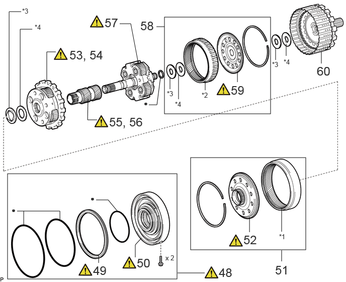
48 CENTER SUPPORT ASSEMBLY WITH 1ST AND REVERSE BRAKE PISTON 35620 (Click here) - -
49 1ST AND REVERSE BRAKE PISTON 35623S (Click here) - -
50 INSPECT CENTER SUPPORT ASSEMBLY 35620 (Click here) - -
51 CENTER PLANETARY RING GEAR WITH CENTER PLANETARY RING GEAR FLANGE 35763 - - -
52 CENTER PLANETARY RING GEAR FLANGE 35769 (Click here) - -
53 REMOVE CENTER PLANETARY GEAR ASSEMBLY 35750 - - -
54 INSPECT CENTER PLANETARY GEAR ASSEMBLY 35750 (Click here) - -
55 REMOVE PLANETARY SUN GEAR SUB-ASSEMBLY 35706H - - -
56 INSPECT PLANETARY SUN GEAR SUB-ASSEMBLY 35706H (Click here) - -
57 INSPECT REAR PLANETARY GEAR ASSEMBLY 35760 (Click here) - -
58 REAR PLANETARY RING GEAR WITH REAR PLANETARY RING GEAR FLANGE 35761 - - -
59 REAR PLANETARY RING GEAR FLANGE 35762 (Click here) - -
60 REAR MULTIPLE DISC CLUTCH ASSEMBLY 35650 - - -

*1 CENTER PLANETARY RING GEAR *2 REAR PLANETARY RING GEAR
*3 THRUST NEEDLE ROLLER BEARING *4 THRUST BEARING RACE
● Non-reusable part - -

C456988C02
3.75,5.313 3.75,4.625 false 3.75,5.115 2.635,5.115 2.635,5.115 2.635,4.927 false 2.948,5.115 2.948,4.854 false 3.208,5.115 3.208,4.781 false 3.479,5.115 3.479,4.729 false 2.24,5.271 2.24,5.01 false 2.604,3.948 2.604,3.448 2.604,3.448 4.021,3.448 false 2.823,3.865 2.823,3.448 false 3.052,3.781 3.052,3.448 false 3.344,3.729 3.344,3.448 false 3.615,3.635 3.615,3.448 false 4.104,1 4.104,0.49 4.104,0.49 4.365,0.49 false 1.896,1.688 1.896,1.167 1.896,1.167 2.292,1.167 false 1.156,2.896 1.156,2.656 false 4.938,4.594 4.938,4.188 false 6.26,4.583 6.26,3.604 false 6.26,4.281 5.729,4.281 5.729,4.281 5.729,4.021 false 5.26,1.938 5.26,1.385 false 5.26,1.646 5.854,1.646 5.854,1.646 5.854,1.208 false 5.563,1.646 5.563,1.292 false 2.885,2.625 2.885,2.188 false 2.885,2.344 3.396,2.344 3.396,2.344 3.396,1.875 false 0.083,0.073 0.333,0.323 0.25,0.25 10 false *A 3.625,5.354 4.521,5.688 0.896,0.333 18 false 61, 62 4.063,3.354 4.281,3.615 0.219,0.26 10 false *1 2.156,5.292 2.375,5.552 0.219,0.26 10 false *2 4.385,0.406 4.646,0.635 0.26,0.229 10 false *3 1.146,2.896 1.531,3.208 0.385,0.313 18 false 64 4.854,4.604 5.073,4.885 0.219,0.281 10 false *4 5.219,1.927 5.375,2.125 0.156,0.198 10 false ● 6.219,4.573 6.375,4.771 0.156,0.198 10 false ● 2.833,2.604 2.99,2.802 0.156,0.198 10 false ● 2.552,1.063 2.938,1.375 0.385,0.313 18 false 63

Procedure Part Name Code
Z101186

Z101188

Z101187

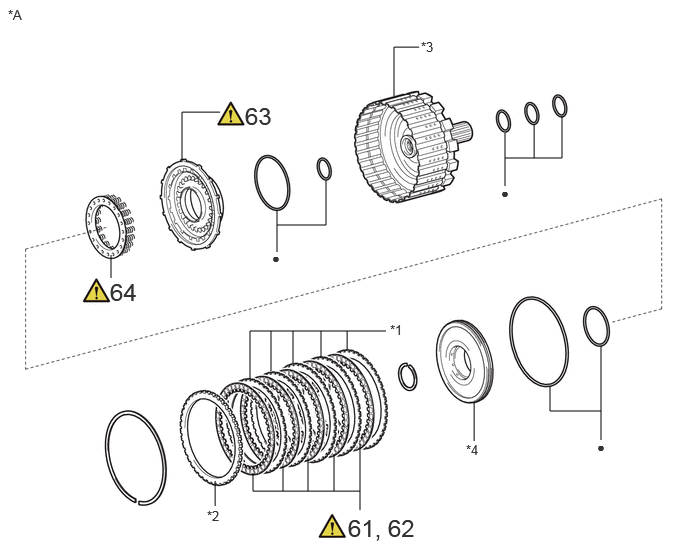
61 REMOVE NO. 4 CLUTCH DISC 35883C (Click here) - -
62 INSPECT NO. 4 CLUTCH DISC 35883C (Click here) - -
63 C-4 CLUTCH PISTON 34638 (Click here) - -
64 INSPECT FORWARD CLUTCH RETURN SPRING SUB-ASSEMBLY (C-4 CLUTCH) 35603A (Click here) - -

*A REAR MULTIPLE DISC CLUTCH ASSEMBLY - -
*1 NO. 4 CLUTCH PLATE *2 CLUTCH FLANGE
*3 OUTPUT SHAFT ASSEMBLY *4 C-4 CLUTCH BALANCER
● Non-reusable part - -

C460370C01
5.813,2.563 5.958,2.563 5.958,2.563 6.063,2.833 false 5.958,4.344 5.833,4.052 5.833,4.052 5.708,4.052 false 4.417,4.823 4.573,4.438 4.573,4.438 4.74,4.438 false 3.042,5.24 3.042,4.875 false 0.885,4.083 0.885,3.75 false 6.271,2.854 6.271,2.417 6.271,2.417 6.458,2.417 false 6.146,4.323 6.146,3.896 6.146,3.896 6.313,3.896 false 4.5,4.896 4.948,4.896 false 6.729,1.458 6.729,1.375 6.729,1.375 6.542,1.26 false 5.667,1.729 5.667,1.583 5.667,1.583 5.51,1.417 false 3.333,2.615 3.333,1.74 3.333,1.74 3.521,1.74 false 5.656,2.458 5.813,2.656 0.156,0.198 10 false ● 6.344,2.76 6.656,2.99 0.313,0.229 10 false x 2 6.063,2.906 6.375,3.135 0.313,0.229 10 false x 2 4.448,4.917 4.792,5.115 0.344,0.198 10 false x 13 4.135,4.875 4.49,5.135 0.354,0.26 10 false x 13 4.771,4.333 4.927,4.531 0.156,0.198 10 false ● 5.573,3.948 5.729,4.146 0.156,0.198 10 false ● 6.49,1.521 6.646,1.719 0.156,0.198 10 false ● 0.656,4.188 0.813,4.385 0.156,0.198 10 false ● 5.427,1.833 5.583,2.031 0.156,0.198 10 false ● 6.188,4.26 6.5,4.49 0.313,0.229 10 false x 2 5.927,4.438 6.24,4.667 0.313,0.229 10 false x 2 3.75,1.604 4.167,1.979 0.417,0.375 18 false 69 0.792,4.135 1.198,4.49 0.406,0.354 18 false 67 2.917,5.271 3.323,5.625 0.406,0.354 18 false 65 6.604,1.479 7.01,1.833 0.406,0.354 18 false 66 5.542,1.76 5.948,2.115 0.406,0.354 18 false 67 6.729,2.313 7.146,2.688 0.417,0.375 18 false 68 6.615,3.792 7.031,4.167 0.417,0.375 18 false 68 5.208,4.76 5.625,5.135 0.417,0.375 18 false 68

Procedure Part Name Code
Z101186

Z101188

Z101187

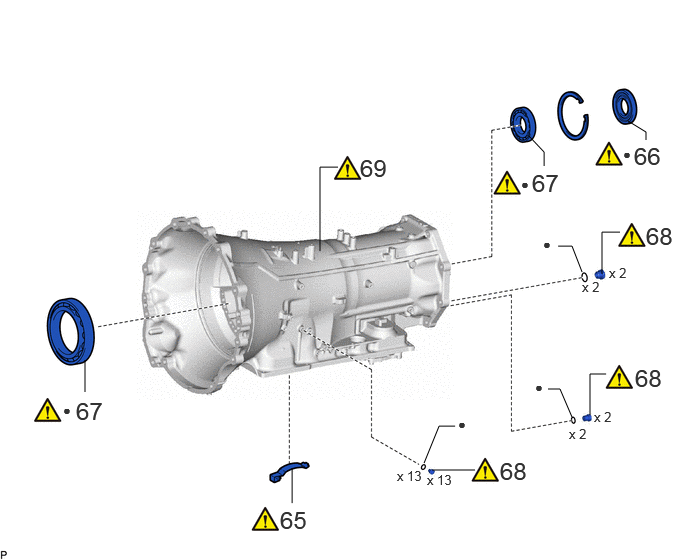
65 BRAKE PLATE STOPPER SPRING 35639B (Click here) - -
66 TRANSMISSION CASE OIL SEAL 33111F (Click here) - -
67 BALL BEARING 35701C (Click here) - -
68 AUTOMATIC TRANSMISSION CASE PLUG 35141B (Click here) - -
69 INSPECT AUTOMATIC TRANSMISSION CASE SUB-ASSEMBLY 35104 (Click here) - -

● Non-reusable part - -

PROCEDURE

Hide 1.SECURE AUTOMATIC TRANSMISSION ASSEMBLY
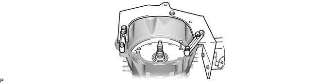
a.
C455663


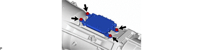
Hide 89530C 2.REMOVE TCM

a.
C455625


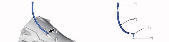
Hide 3.REMOVE BREATHER PLUG SUB-ASSEMBLY

a.
C455626C01
5,0.167 5.667,0.167 false 5.083,1.083 5.51,0.833 5.51,0.833 5.667,0.833 false 5.667,1.448 6.094,1.198 6.094,1.198 6.25,1.198 false 5.688,1.656 6.354,1.656 false 5.708,0.073 6.021,0.229 0.313,0.156 10 false *1 6.281,1.115 6.594,1.271 0.313,0.156 10 false *2 5.688,0.74 6,0.896 0.313,0.156 10 false *3 6.375,1.552 6.688,1.708 0.313,0.156 10 false *4
*1 No. 1 Breather Plug (ATM) *2 No. 2 Breather Plug (ATM)
*3 Breather Plug Hose *4 O-ring


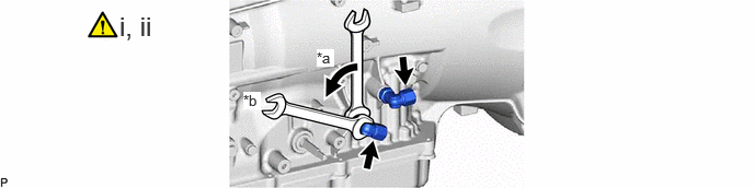
Hide 4.REMOVE OIL COOLER TUBE UNION

a.
C460374C01
3.01,0.469 3.177,0.635 0.167,0.167 10 true *a 2.313,0.875 2.479,1.042 0.167,0.167 10 true *b 1.135,0.104 2.51,0.458 1.375,0.354 18 false i, ii
*a Turn *b Hold


i.

Remove the 2 oil cooler tube unions from the automatic transmission case sub-assembly.


ii.

Remove the 2 O-rings from the 2 oil cooler tube unions.


Hide 84540 5.REMOVE PARK/NEUTRAL POSITION SWITCH ASSEMBLY

Z101186

NOTICE:
·

When reusing the park/neutral position switch assembly, try not to remove the park/neutral position switch assembly.

·

When removing the parts related to the parking lock, remove the park/neutral position switch assembly.

·

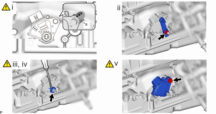
When reusing the park/neutral position switch assembly, put matchmarks on the park/neutral position switch assembly and automatic transmission case sub-assembly.


a.
C468567C01
2.573,0.51 2.792,0.688 2.792,0.688 2.656,0.448 true 2.063,0.083 2.344,0.438 0.281,0.354 18 false i 0.417,1.99 1,2.323 0.583,0.333 18 true iii, iv 3.792,1.958 4.073,2.313 0.281,0.354 18 false v 0.385,0.083 0.542,0.469 0.156,0.385 18 true i 3.885,0.104 4.042,0.49 0.156,0.385 18 false ii 2.771,0.719 2.979,0.948 0.208,0.229 10 true *a
*a Matchmark - -


i.

When reusing the park/neutral position switch assembly, put matchmarks on the park/neutral position switch assembly and automatic transmission case sub-assembly.


ii.

Remove the nut, spring washer and transmission control shaft lever RH.


iii.

Using a screwdriver, pry out the lock washer.

NOTICE:

Be careful not to damage the park/neutral position switch assembly.


HINT:

Tape the screwdriver tip before use.


iv.

Remove the nut and lock washer.


v.

Remove the bolt and park/neutral position switch assembly from the automatic transmission case sub-assembly.

HINT:

Make sure that the manual valve lever shaft has not been rotated prior to installing the park/neutral position switch assembly as the detent spring may become detached from the manual valve lever shaft.


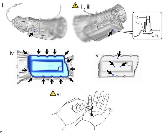
Hide 35106 6.REMOVE AUTOMATIC TRANSMISSION OIL PAN SUB-ASSEMBLY
a.
C459161C01
6.125,0.771 6.458,0.771 false 6.521,1.458 6.698,1.604 6.698,1.604 6.781,1.604 false 6.125,1.01 6.208,1.01 6.208,1.01 6.323,1.365 true 6.823,1.5 7.135,1.656 0.313,0.156 10 false *1 5.958,0.688 6.271,0.844 0.313,0.156 10 false *2 5.969,0.917 6.281,1.073 0.313,0.156 10 false *3 0.083,0.073 1.458,0.427 1.375,0.354 18 false i 0.427,2.177 1.802,2.531 1.375,0.354 18 false iv 2.49,3.969 3.865,4.323 1.375,0.354 18 false vi 3.563,0.135 4.135,0.438 0.573,0.302 18 true ii, iii 4.208,2.271 5.583,2.625 1.375,0.354 18 false v
*1 Overflow Plug *2 No. 1 Transmission Oil Filler Tube
*3 Gasket - -


i.

Remove the refill plug and gasket from the automatic transmission case sub-assembly.


ii.

Using a 6 mm hexagon socket wrench, remove the overflow plug and gasket from the automatic transmission assembly.


iii.

Using a 6 mm hexagon socket wrench, remove the No. 1 transmission oil filler tube from the automatic transmission assembly.


iv.

Remove the 13 bolts, automatic transmission oil pan sub-assembly and automatic transmission oil pan gasket from the automatic transmission case sub-assembly.


v.

Remove the 4 transmission oil cleaner magnets from the automatic transmission oil pan sub-assembly.


vi.

Examine the particles in the automatic transmission oil pan sub-assembly.

1.

Use the removed transmission oil cleaner magnets to collect any steel chips.

Examine the chips and particles in the automatic transmission oil pan sub-assembly and on the transmission oil cleaner magnets to determine what type of wear might be found in the automatic transmission assembly.

Result:
Steel (magnetic):

Bearing, gear and clutch plate wear

Brass (non-magnetic):

Bushing wear


Hide 35330 7.REMOVE VALVE BODY OIL STRAINER ASSEMBLY

Hide 33129G 8.REMOVE NO. 2 TRANSMISSION OIL PIPE (w/ Stop And Start System)
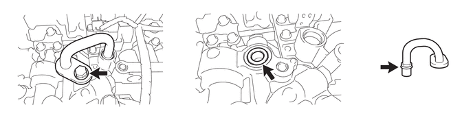
a.
C459126


Hide 33129H 9.REMOVE NO. 3 TRANSMISSION OIL PIPE (w/ Stop And Start System)
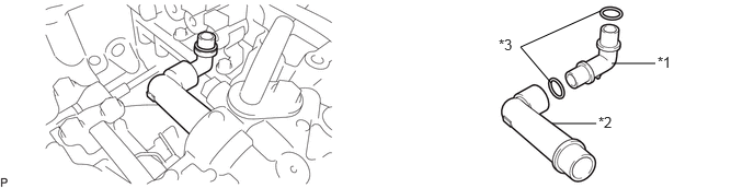
a.
C456967C01
5.24,0.792 4.948,0.448 4.948,0.448 5.708,0.104 false 5.813,0.604 6.229,0.604 false 5.25,1.177 5.667,1.177 false 6.25,0.51 6.563,0.667 0.313,0.156 10 false *1 5.688,1.083 6,1.24 0.313,0.156 10 false *2 4.74,0.344 5.052,0.5 0.313,0.156 10 false *3
*1 No. 3 Transmission Oil Pipe *2 No. 4 Transmission Oil Pipe
*3 O-ring - -


Hide 35300D 10.REMOVE OIL PUMP WITH MOTOR ASSEMBLY (w/ Stop And Start System)
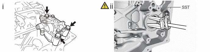
a.
C456966N02
5.333,0.594 5.75,0.25 5.75,0.25 6.167,0.25 true 0.073,0.073 0.354,0.427 0.281,0.354 18 false i 6.208,0.167 6.677,0.521 0.469,0.354 10 false SST 3.75,0.063 4.031,0.417 0.281,0.354 18 false ii

i.

Remove the 3 bolts and oil pump with motor assembly from the automatic transmission case sub-assembly.


ii.

Using SST, remove the oil seal from the automatic transmission case sub-assembly.

SST
09308-00010  


Hide 35400A 11.REMOVE TRANSMISSION VALVE BODY ASSEMBLY

Z101186

Click here(Click here)

Hide 89413V 12.REMOVE TRANSMISSION REVOLUTION SENSOR (SP2)

Hide 89413N 13.REMOVE TRANSMISSION REVOLUTION SENSOR (NT)

Hide 82125J 14.REMOVE TRANSMISSION WIRE

Z101186

(Click here)

Hide 33129F 15.REMOVE TRANSMISSION OIL PIPE
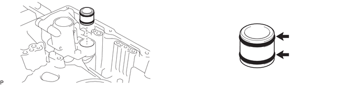
a.
C455628


Hide 35595 16.REMOVE PARKING LOCK PAWL BRACKET

a.
C455629


Hide 35501 17.REMOVE PARKING LOCK ROD SUB-ASSEMBLY

a.
C456976C01
2.552,0.646 2.75,0.219 2.75,0.219 2.833,0.219 true 2.927,0.5 3.042,0.354 3.042,0.354 3.125,0.354 true 3.188,0.26 3.375,0.49 0.188,0.229 10 true *1 2.875,0.135 3.094,0.313 0.219,0.177 10 true *2
*1 Manual Valve Lever Sub-assembly *2 Parking Lock Rod Sub-assembly


Hide 35556 18.REMOVE PARKING LOCK PAWL SHAFT

a.
C455631C01
3.917,0.25 4.333,0.167 4.333,0.167 4.5,0.167 false 2.083,0.667 2.167,0.667 2.167,0.667 2.688,0.844 false 3,0.708 3.167,0.667 3.167,0.667 3.333,0.667 true 2,1.052 2.083,1.052 2.083,1.052 2.385,1.135 false 4.521,0.073 4.833,0.229 0.313,0.156 10 false *1 3.396,0.594 3.625,0.823 0.229,0.229 10 true *2 1.833,0.938 2.146,1.094 0.313,0.156 10 false *3 1.927,0.583 2.24,0.74 0.313,0.156 10 false *4
*1 Parking Lock Pawl *2 Parking Lock Pawl Shaft
*3 Spring *4 E-ring


Hide 35505 19.REMOVE MANUAL VALVE LEVER SUB-ASSEMBLY
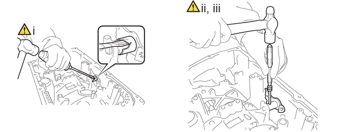
a.
C455633N01
4.26,0.021 4.813,0.375 0.552,0.354 18 true ii, iii 0.688,0.5 0.823,0.802 0.135,0.302 18 true i

i.

Using a screwdriver and a hammer, cut off the spacer and remove it from the manual valve lever shaft.

NOTICE:

Be careful not to damage the manual valve lever shaft.


HINT:

Tape the screwdriver tip before use.


ii.

Using a 3 mm pin punch and hammer, remove the spring pin from the manual valve lever shaft.

HINT:

Slowly tap out the spring pin so that it does not fall into the automatic transmission case sub-assembly.


iii.

Remove the manual valve lever shaft and manual valve lever sub-assembly from the automatic transmission case sub-assembly.


Hide 35308K 20.REMOVE NO. 2 FRONT OIL PUMP COVER SUB-ASSEMBLY
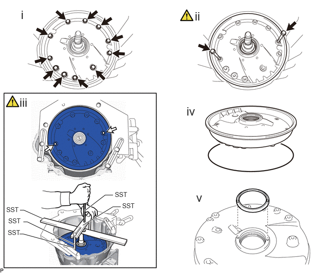
a.
C459101C01
1.802,4.51 2.25,4.167 2.25,4.167 2.417,4.167 true 1.771,4.813 2.417,4.417 2.417,4.417 2.583,4.417 true 0.427,4.49 0.51,4.49 0.51,4.49 0.927,4.677 true 0.5,4.74 0.583,4.74 0.583,4.74 1.594,5.229 true 0.417,5 0.5,5 0.5,5 1.573,5.292 true 0.448,0.167 0.781,0.625 0.333,0.458 18 false i 4.167,0.198 4.5,0.656 0.333,0.458 18 false ii 0.417,2.042 0.75,2.5 0.333,0.458 18 false iii 3.99,2.229 4.323,2.688 0.333,0.458 18 false iv 2.458,4.073 2.917,4.271 0.458,0.198 10 false SST 2.615,4.313 3.073,4.51 0.458,0.198 10 false SST 0.135,4.396 0.594,4.594 0.458,0.198 10 false SST 0.177,4.635 0.635,4.833 0.458,0.198 10 false SST 0.167,4.885 0.625,5.083 0.458,0.198 10 false SST 4.198,4.073 4.531,4.531 0.333,0.458 18 false v
V100136

SST bolt installation position - -


i.

Remove the 11 bolts from the No. 2 front oil pump cover sub-assembly.


ii.

Temporarily install the 2 bolts to the position shown in the illustration and remove the No. 2 front oil pump cover sub-assembly.

HINT:

Use an M10 x 1.25 bolt.


iii.

If the No. 2 front oil pump cover sub-assembly is stuck and cannot be detached:

Using SST, rotate and remove the No. 2 front oil pump cover sub-assembly by hand as shown in the illustration.

SST
09380-60012  (09381-06010, 09381-06050, 09381-06120)
09950-50013  (09955-05010)
09322-35010  (09322-03030)


iv.

Remove the O-ring from the No. 2 front oil pump cover sub-assembly.


v.

Remove the gear thrust washer from the No. 2 front oil pump cover sub-assembly.


Hide 21.REMOVE DRIVE SPROCKET AND TRANSMISSION DRIVE CHAIN
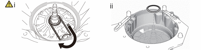
a.
C455639C01
0.49,0.021 0.771,0.375 0.281,0.354 18 false i 3.917,0.063 4.198,0.417 0.281,0.354 18 false ii
V113147

Remove While Rotating - -


i.

While rotating the transmission drive chain, remove the drive sprocket and transmission drive chain.


ii.

Remove the gear thrust washer from the stator shaft assembly.


Hide 22.REMOVE OIL PUMP ASSEMBLY WITH DRIVEN SPROCKET

a.
C455637


Hide 35781C 23.INSPECT TRANSMISSION DRIVE CHAIN

Z101186

(Click here)

Hide 35782 24.INSPECT DRIVE SPROCKET

Z101186

(Click here)

Hide 35370 25.REMOVE STATOR SHAFT ASSEMBLY

a.
C455640C01
3.75,2.25 5.083,2.25 false 3.76,2.531 5.094,2.531 true 3.75,1.583 4.583,1.583 false 3.583,2.156 3.896,2.313 0.313,0.156 10 false *2 3.604,2.438 3.917,2.594 0.313,0.156 10 false *3 3.573,1.479 3.885,1.635 0.313,0.156 10 false *1 0.521,0.167 0.802,0.521 0.281,0.354 18 false i 3.771,0.729 4.052,1.083 0.281,0.354 18 false ii 0.563,2.385 0.844,2.74 0.281,0.354 18 false iii
*1 Stator Shaft Assembly *2 Thrust Bearing Race
*3 Thrust Needle Roller Bearing - -


i.

Using a T50 "TORX" socket wrench, remove the 2 screws.


ii.

Remove the stator shaft assembly, thrust bearing race and thrust needle roller bearing from the automatic transmission case sub-assembly.


iii.

Remove the oil seal ring from the stator shaft assembly.


Hide 35370 26.INSPECT STATOR SHAFT ASSEMBLY

Z101186

Click here(Click here)

Hide 35681A 27.REMOVE NO. 1 BRAKE DISC

a.
C455642C01
4.729,0.25 5.063,0.25 false 4.667,0.583 5.083,0.583 5.083,0.583 5.083,1.5 false 3.667,1 4.083,1 false 4.667,1.167 5.083,1.167 false 4.667,1.365 5.083,1.365 false 4.083,0.781 3.667,0.781 3.667,0.781 3.667,1.583 false 3.667,1.229 4.083,1.229 false 3.667,1.417 4.083,1.417 false 4.667,0.917 5.083,0.917 false 5,1.531 5.313,1.688 0.313,0.156 10 false *1 3.594,1.604 3.906,1.76 0.313,0.156 10 false *2 5.104,0.146 5.417,0.302 0.313,0.156 10 false *3 0.375,0.073 0.646,0.427 0.271,0.354 18 false i 3.615,0.052 3.885,0.406 0.271,0.354 18 false ii
*1 No. 1 Brake Disc *2 No. 1 Brake Plate
*3 No. 1 Brake Flange - -


i.

Using a screwdriver, remove the snap ring from the front support sub-assembly.

NOTICE:

Be careful not to damage the front support sub-assembly.


HINT:

Tape the screwdriver tip before use.


ii.

Remove the 4 No. 1 brake plates, 4 No. 1 brake discs and No. 1 brake flange from the front support sub-assembly.


Hide 35681A 28.INSPECT NO. 1 BRAKE DISC

Z101186

(Click here)

Hide 35608J 29.REMOVE BRAKE PISTON RETURN SPRING SUB-ASSEMBLY (NO. 1 BRAKE)
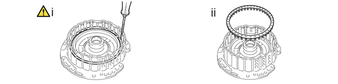
a.
C455644N01
1.083,0.104 1.25,0.448 0.167,0.344 18 false i 4.469,0.115 4.854,0.615 0.385,0.5 18 false ii

i.

Using a screwdriver, remove the snap ring from the front support sub-assembly.

NOTICE:

Be careful not to damage the front support sub-assembly.


HINT:

Tape the screwdriver tip before use.


ii.

Remove the brake piston return spring sub-assembly (No. 1 brake) from the front support sub-assembly.


Hide 35608J 30.INSPECT BRAKE PISTON RETURN SPRING SUB-ASSEMBLY (NO. 1 BRAKE)

Z101186

(Click here)

Hide 35621 31.REMOVE NO. 1 BRAKE PISTON

a.
C456956C01
0.052,0.042 7.073,3.875 7.021,3.833 1.427,0.656 2.677,0.656 true 5.333,2.167 5.583,2.167 5.583,2.167 5.844,1.792 true 5.781,0.292 6.031,0.292 6.031,0.292 6.344,1.031 true 2.49,1.75 2.99,1.75 true 0.406,0.094 0.688,0.448 0.281,0.354 18 false i 2.417,3.979 2.698,4.333 0.281,0.354 18 false ii 0.5,0.448 0.813,0.646 0.313,0.198 10 false *A 4.677,0.51 4.99,0.708 0.313,0.198 10 false *B 2.771,0.563 3.083,0.76 0.313,0.198 10 false *a 5.146,2.042 5.458,2.24 0.313,0.198 10 false *a 5.594,0.177 5.906,0.375 0.313,0.198 10 false *b 2.323,1.646 2.698,1.99 0.375,0.344 10 false *1
*A Front Side *B Rear Side
*1 No. 1 Brake Piston - -
*a Cover the oil hole *b Blow air into the oil hole


i.

While holding the No. 1 brake piston, apply compressed air to the oil hole of the front support sub-assembly to remove the No. 1 brake piston from the front support sub-assembly.


ii.

Remove the 2 O-rings from the front No. 1 brake piston.


Hide 35720 32.REMOVE FRONT PLANETARY GEAR ASSEMBLY
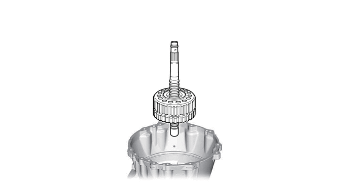
a.
C455646


Hide 35710G 33.REMOVE PLANETARY SUN GEAR ASSEMBLY
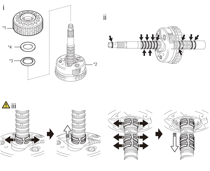
a.
C456969C01
0.24,0.969 0.49,0.969 false 2.906,2.208 3.156,2.208 false 0.479,2.073 0.729,2.073 false 0.49,1.604 0.74,1.604 false 0.083,0.865 0.396,1.021 0.313,0.156 10 false *1 3.188,2.104 3.5,2.26 0.313,0.156 10 false *2 0.313,1.99 0.625,2.146 0.313,0.156 10 false *3 0.271,1.521 0.583,1.677 0.313,0.156 10 false *4 0.094,0.104 0.375,0.458 0.281,0.354 18 false i 3.521,0.438 3.802,0.792 0.281,0.354 18 false ii 0.385,3.458 0.979,3.938 0.594,0.479 18 false iii
*1 Planetary Sun Gear Assembly *2 Front Planetary Gear Assembly
*3 Thrust Bearing Race *4 Thrust Needle Roller Bearing
V113147

Expand the opening of the bearing
V113148

Remove in this direction


i.

Remove the planetary sun gear assembly, thrust bearing race and thrust needle roller bearing from the front planetary gear assembly.


ii.

Remove the 11 oil seal rings from the front planetary gear assembly.


iii.

Remove the 4 needle roller bearings from the front planetary gear assembly as shown in the illustration.


Hide 35720 34.INSPECT FRONT PLANETARY GEAR ASSEMBLY

Z101186

(Click here)

Hide 35706P 35.REMOVE FRONT PLANETARY SUN GEAR SUB-ASSEMBLY

a.
C455645C01
3.771,0.177 4.688,0.177 false 3.76,0.427 4.677,0.427 false 3.792,0.781 4.625,0.781 true 4.656,0.688 4.969,0.844 0.313,0.156 10 false *1 4.708,0.333 5.021,0.49 0.313,0.156 10 false *2 4.708,0.083 5.021,0.24 0.313,0.156 10 false *3
*1 Front Planetary Sun Gear Sub-assembly *2 Thrust Bearing Race
*3 Thrust Needle Roller Bearing - -


Hide 35706P 36.INSPECT FRONT PLANETARY SUN GEAR SUB-ASSEMBLY

Z101186

(Click here)

Hide 35753B 37.REMOVE FRONT PLANETARY OIL RECEIVER
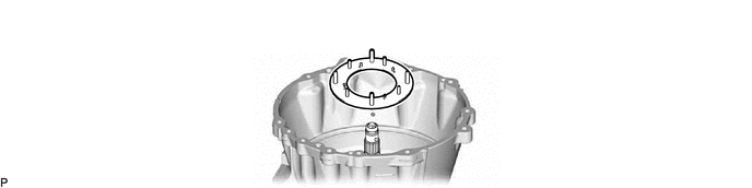
a.
C455652


Hide 35743 38.REMOVE FRONT PLANETARY RING GEAR WITH C-1 CLUTCH ASSEMBLY
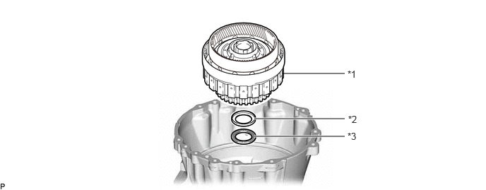
a.
C455653C01
4.167,1.083 5.083,1.083 false 3.75,1.75 5.083,1.75 true 3.75,2.01 5.083,2.01 true 5.125,1.01 5.438,1.167 0.313,0.156 10 false *1 5.135,1.677 5.448,1.833 0.313,0.156 10 false *2 5.125,1.927 5.438,2.083 0.313,0.156 10 false *3
*1 Front Planetary Ring Gear with C-1 Clutch Assembly *2 Thrust Bearing Race
*3 Thrust Needle Roller Bearing - -


Hide 35743 39.REMOVE FRONT PLANETARY RING GEAR
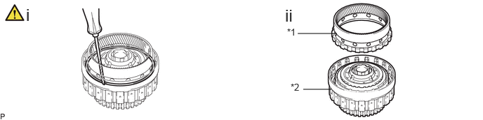
a.
C455654C01
4.417,0.5 5,0.5 false 4.5,1.333 4.917,1.333 false 4.26,0.396 4.573,0.552 0.313,0.156 10 false *1 4.313,1.219 4.625,1.375 0.313,0.156 10 false *2 0.385,0.073 0.813,0.458 0.427,0.385 18 false i 4.229,0.083 4.656,0.469 0.427,0.385 18 false ii
*1 Front Planetary Ring Gear *2 C-1 Clutch Assembly with C-2 Drum Sub-assembly


i.

Using a screwdriver, remove the snap ring from the front planetary ring gear with C-1 clutch assembly.

NOTICE:

Be careful not to damage the front planetary ring gear with C-1 clutch assembly.


HINT:

Tape the screwdriver tip before use.


ii.

Remove the front planetary ring gear from the C-1 clutch assembly with C-2 drum sub-assembly.


Hide 3560B 40.REMOVE C-2 DRUM SUB-ASSEMBLY

Z101186

NOTICE:

Do not disassemble the C-1 clutch assembly.

If disassembled, replace the C-1 clutch assembly with a new one.


a.
C455655C01
2.167,2.25 2.833,2.25 false 2.083,0.5 2.75,0.5 false 1.833,1.167 2.75,1.167 false 1.833,1.458 2.75,1.458 false 2.781,0.406 3.167,0.667 0.385,0.26 10 false *1 2.885,2.167 3.198,2.323 0.313,0.156 10 false *2 2.771,1.073 3.083,1.229 0.313,0.156 10 false *3 2.771,1.365 3.083,1.521 0.313,0.156 10 false *4
*1 C-2 Clutch Assembly with C-2 Drum Sub-assembly *2 C-1 Clutch Assembly
*3 Thrust Needle Roller Bearing *4 Thrust Bearing Race


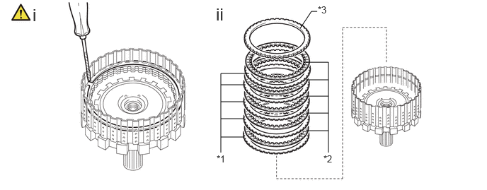
Hide 35610 41.INSPECT C-1 CLUTCH ASSEMBLY

Z101186

(Click here)

Hide 35650L 42.REMOVE C-2 CLUTCH ASSEMBLY

a.
C459139C01
2.375,0.594 2.958,0.594 false 2.615,1.292 3.198,1.292 false 2.646,1.688 3.229,1.688 false 2.542,2.375 3.125,2.375 false 2.198,0.49 2.458,0.802 0.26,0.313 10 false *1 2.344,2.292 2.635,2.604 0.292,0.313 10 false *2 2.438,1.177 2.688,1.625 0.25,0.448 10 false *3 2.458,1.604 2.771,1.906 0.313,0.302 10 false *4
*1 C-2 Clutch Assembly *2 C-2 Drum Sub-assembly
*3 Thrust Needle Roller Bearing *4 Thrust Bearing Race


Hide 35640 43.REMOVE C-3 CLUTCH ASSEMBLY

a.
C455659


Hide 35682A 44.REMOVE NO. 2 BRAKE DISC

a.
C455658C01
4.031,1.083 5.115,1.083 false 4.281,1.083 4.281,2.583 4.281,2.583 5.115,2.583 false 4.281,1.417 5.115,1.417 false 4.281,1.833 5.115,1.833 false 4.292,2.229 5.125,2.229 false 5.885,0.635 6.469,0.635 false 5.833,0.917 6.531,0.917 false 6.354,0.917 6.354,2.417 6.354,2.417 5.865,2.417 false 5.854,1.25 6.354,1.25 false 5.854,1.635 6.354,1.635 false 5.854,2.031 6.354,2.031 false 6.583,0.833 6.896,0.99 0.313,0.156 10 false *1 3.854,0.979 4.167,1.135 0.313,0.156 10 false *2 6.51,0.542 6.823,0.698 0.313,0.156 10 false *3 0.385,1.031 0.719,1.563 0.333,0.531 18 false i 3.844,0.458 4.177,0.99 0.333,0.531 18 false ii
*1 No. 2 Brake Disc *2 No. 2 Brake Plate
*3 No. 2 Brake Flange - -


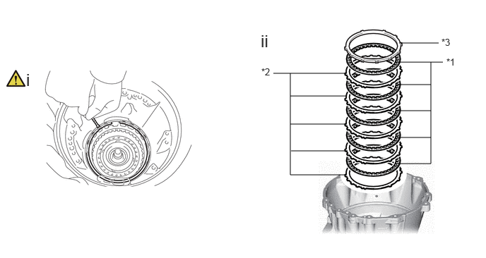
i.

Using a screwdriver, remove the snap ring from the automatic transmission case sub-assembly.

NOTICE:

Be careful not to damage the automatic transmission case sub-assembly.


HINT:

Tape the screwdriver tip before use.


ii.

Remove the 5 No. 2 brake plates, 5 No. 2 brake discs and No. 2 brake flange from the automatic transmission case sub-assembly.


Hide 35682A 45.INSPECT NO. 2 BRAKE DISC

Z101186

(Click here)

Hide 35622G 46.REMOVE NO. 2 BRAKE PISTON

a.
C456970N01
1.25,1.083 1.417,1.083 1.417,1.083 1.583,1.333 true 1.917,0.333 2.083,0.333 false 2.563,0.927 2.635,0.469 2.635,0.469 2.802,0.469 true 1.875,1.646 2.354,1.354 2.354,1.354 2.521,1.354 true 1.938,1.896 2.313,1.698 2.313,1.698 2.479,1.698 true 2,2.125 2.333,1.99 2.333,1.99 2.5,1.99 true 2.083,2.188 2.479,2.458 2.479,2.458 2.646,2.458 true 1.823,2.26 2.198,2.74 2.198,2.74 2.365,2.74 true 0.427,0.208 0.948,0.531 0.521,0.323 18 true i, ii 3.906,0.208 4.24,0.604 0.333,0.396 18 true iv 0.469,3.729 0.802,4.125 0.333,0.396 18 false iii 4.01,2.427 4.229,2.719 0.219,0.292 18 true v 3.927,4.344 4.26,4.74 0.333,0.396 18 true vi 2.146,0.25 2.531,0.479 0.385,0.229 10 true SST 0.917,1 1.229,1.219 0.313,0.219 10 true SST 2.865,0.365 3.25,0.594 0.385,0.229 10 true SST 2.552,1.26 2.938,1.49 0.385,0.229 10 true SST 2.521,1.573 2.906,1.802 0.385,0.229 10 true SST 2.542,1.854 2.927,2.083 0.385,0.229 10 true SST 2.698,2.354 3.083,2.583 0.385,0.229 10 true SST 2.417,2.635 2.802,2.865 0.385,0.229 10 false SST

i.

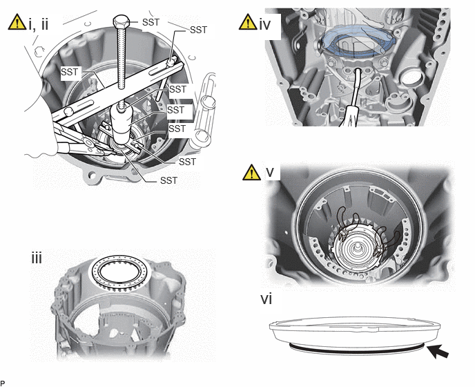
Set SST on the brake piston return spring sub-assembly (No. 2 brake), automatic transmission case sub-assembly and tighten SST to compress the brake piston return spring sub-assembly (No. 2 brake).

SST
09308-14010  
09380-60012  (09381-06010, 09381-06020, 09381-06040, 09381-06050, 09381-06090, 09381-06120, 09381-06140)


ii.

Using snap ring expander, remove the hole snap ring from the center support assembly.


iii.

Remove the brake piston return spring sub-assembly (No. 2 brake) from the No. 2 brake piston.


iv.

While holding the automatic transmission case sub-assembly, apply compressed air (400 kPa (4.1 kgf/cm2, 58 psi)) to the oil hole to the No. 2 brake piston to lift it from the center support assembly.

HINT:

While evenly and lightly pressing on the No. 2 brake piston using your hand, blow in air a little at a time to remove the No. 2 brake piston smoothly.


v.

Using 2 needle-nose pliers, remove the No. 2 brake piston from the center support assembly.

NOTICE:

Be careful not to damage the No. 2 brake piston.


HINT:

Tape the tip of needle-nose pliers before use.


vi.

Remove the O-ring from the No. 2 brake piston.


Hide 35608J 47.INSPECT BRAKE PISTON RETURN SPRING SUB-ASSEMBLY (NO. 2 BRAKE)

Z101186

(Click here)

Hide 35620 48.REMOVE CENTER SUPPORT ASSEMBLY WITH 1ST AND REVERSE BRAKE PISTON
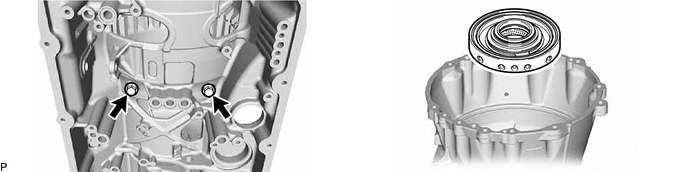
a.
C455664

HINT:
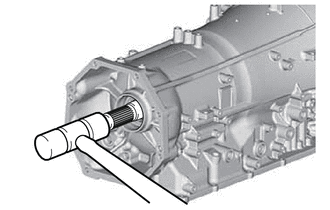
If the center support assembly with 1st and reverse brake piston cannot be lifted up and removed by hand:
C455665

Lightly tap the output shaft using a plastic-faced hammer and remove the center support assembly with 1st and reverse brake piston.


Hide 35623S 49.REMOVE 1ST AND REVERSE BRAKE PISTON
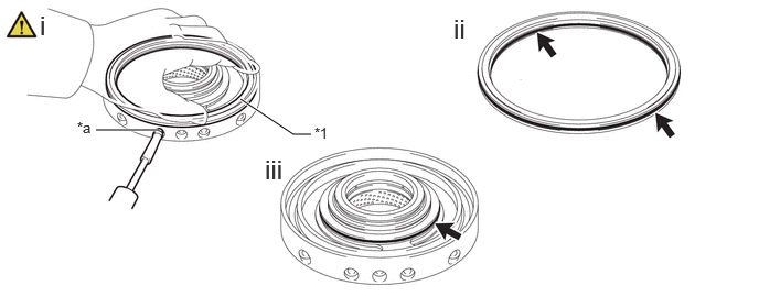
a.
C455666C01
2.271,0.938 2.771,1.271 2.771,1.271 2.938,1.271 true 0.906,1.229 1.49,1.229 true 2.969,1.177 3.281,1.333 0.313,0.156 10 false *1 0.729,1.125 1.042,1.281 0.313,0.156 10 false *a 0.375,0.094 0.656,0.448 0.281,0.354 18 false i 4.281,0.125 4.563,0.479 0.281,0.354 18 false ii 2.5,1.458 2.781,1.813 0.281,0.354 18 false iii
*1 1st and Reverse Brake Piston - -
*a Oil Hole - -


i.

While holding the center support assembly, apply compressed air (400 kPa (4.1 kgf/cm2, 58 psi) to the oil hole to remove the 1st and reverse brake piston from the center support assembly.

HINT:

While evenly and lightly pressing on the 1st and reverse brake piston using your hand, blow in air a little at a time to remove the 1st and reverse brake piston.


ii.

Remove the 2 O-rings from the 1st and reverse brake piston.


iii.

Remove the O-ring from the center support assembly.


Hide 35620 50.INSPECT CENTER SUPPORT ASSEMBLY

Z101186

(Click here)

Hide 35763 51.REMOVE CENTER PLANETARY RING GEAR WITH CENTER PLANETARY RING GEAR FLANGE

a.
C455667


Hide 35769 52.REMOVE CENTER PLANETARY RING GEAR FLANGE
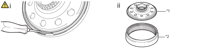
a.
C455668C01
5.667,0.417 6,0.417 false 5.719,1.354 5.969,1.354 false 0.344,0.063 0.865,0.552 0.521,0.49 18 false i 4.24,0.042 4.76,0.531 0.521,0.49 18 false ii 6.021,0.313 6.333,0.51 0.313,0.198 10 false *1 5.99,1.25 6.302,1.448 0.313,0.198 10 false *2
*1 Center Planetary Ring Gear Flange *2 Center Planetary Ring Gear


i.

Using a screwdriver, remove the snap ring from the center planetary ring gear.

NOTICE:

Be careful not to damage the center planetary ring gear.


HINT:

Tape the screwdriver tip before use.


ii.

Remove the center planetary ring gear flange from the center planetary ring gear.


Hide 35750 53.REMOVE CENTER PLANETARY GEAR ASSEMBLY
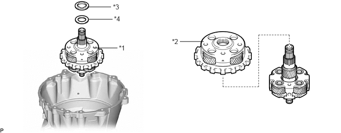
a.
C468573C01
1.833,0.146 2.333,0.146 false 1.865,0.406 2.365,0.406 false 1.969,1.01 2.469,1.01 false 3.781,0.875 4.281,0.875 false 3.615,0.792 3.927,0.948 0.313,0.156 10 false *2 2.375,0.063 2.688,0.219 0.313,0.156 10 false *3 2.5,0.927 2.833,1.156 0.333,0.229 10 false *1 2.396,0.313 2.708,0.469 0.313,0.156 10 false *4
*1 Rear Planetary Gear Assembly with Planetary Sun Gear Sub-assembly and Center Planetary Gear Assembly *2 Center Planetary Gear Assembly
*3 Thrust Bearing Race *4 Thrust Needle Roller Bearing


Hide 35750 54.INSPECT CENTER PLANETARY GEAR ASSEMBLY

Z101186

Click here(Click here)

Hide 35706H 55.REMOVE PLANETARY SUN GEAR SUB-ASSEMBLY
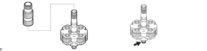
a.
C456917


Hide 35706H 56.INSPECT PLANETARY SUN GEAR SUB-ASSEMBLY

Z101186

Click here(Click here)

Hide 35760 57.INSPECT REAR PLANETARY GEAR ASSEMBLY

Z101186

Click here(Click here)

Hide 35761 58.REMOVE REAR PLANETARY RING GEAR WITH REAR PLANETARY RING GEAR FLANGE
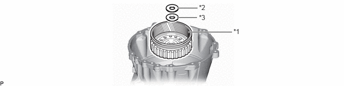
a.
C456975C01
3.917,0.667 4.833,0.667 true 3.698,0.167 4.115,0.167 true 3.688,0.365 4.104,0.365 true 4.865,0.573 5.177,0.729 0.313,0.156 10 false *1 4.146,0.073 4.458,0.229 0.313,0.156 10 false *2 4.146,0.281 4.458,0.438 0.313,0.156 10 false *3
*1 Rear Planetary Ring Gear with Rear Planetary Ring Gear Flange *2 Thrust Needle Roller Bearing
*3 Thrust Bearing Race - -


Hide 35762 59.REMOVE REAR PLANETARY RING GEAR FLANGE
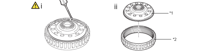
a.
C456919C01
5.167,0.458 5.75,0.458 false 5.26,1.354 5.844,1.354 false 5.781,0.365 6.094,0.521 0.313,0.156 10 false *1 5.896,1.271 6.208,1.427 0.313,0.156 10 false *2 1.385,0.052 1.667,0.406 0.281,0.354 18 false i 3.896,0.073 4.177,0.427 0.281,0.354 18 false ii
*1 Rear Planetary Ring Gear Flange *2 Rear Planetary Ring Gear


i.

Using a screwdriver, remove the snap ring from the rear planetary ring gear.

NOTICE:

Be careful not to damage the rear planetary ring gear.


HINT:

Tape the screwdriver tip before use.


ii.

Remove the rear planetary ring gear flange from the rear planetary ring gear.


Hide 35650 60.REMOVE REAR MULTIPLE DISC CLUTCH ASSEMBLY
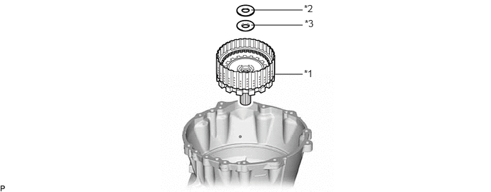
a.
C456920C01
4,1.083 4.417,1.083 false 3.667,0.365 4.417,0.365 false 3.667,0.146 4.417,0.146 false 4.438,0.99 4.75,1.146 0.313,0.156 10 false *1 4.448,0.26 4.76,0.417 0.313,0.156 10 false *3 4.438,0.042 4.75,0.198 0.313,0.156 10 false *2
*1 Rear Multiple Disc Clutch Assembly *2 Thrust Needle Roller Bearing
*3 Thrust Bearing Race - -


Hide 35883C 61.REMOVE NO. 4 CLUTCH DISC

a.
C456921C01
4.5,1.417 4.833,1.417 false 4.5,1.667 4.833,1.667 false 4.5,1.927 4.833,1.927 false 3.667,1.083 3.25,1.083 3.25,1.083 3.25,2.25 false 3.25,1.5 3.583,1.5 false 3.25,1.75 3.583,1.75 false 4.667,0.167 4.583,0.167 4.583,0.167 4.417,0.417 false 3.25,2.021 3.583,2.021 false 3.25,1.25 3.583,1.25 false 4.5,0.917 4.833,0.917 4.833,0.917 4.833,2.25 false 4.5,1.177 4.833,1.177 false 3.188,2.26 3.5,2.417 0.313,0.156 10 false *1 4.76,2.26 5.073,2.417 0.313,0.156 10 false *2 4.677,0.063 5.021,0.313 0.344,0.25 10 false *3 0.479,0.073 0.885,0.594 0.406,0.521 18 false i 3.177,0.063 3.583,0.583 0.406,0.521 18 false ii
*1 No. 4 Clutch Plate *2 No. 4 Clutch Disc
*3 Clutch Flange - -


i.

Using a screwdriver, remove the snap ring from the output shaft assembly.

NOTICE:

Be careful not to damage the output shaft assembly.


HINT:

Tape the screwdriver tip before use.


ii.

Remove the 5 No. 4 clutch plates, 5 No. 4 clutch discs and clutch flange from the output shaft assembly.


Hide 35883C 62.INSPECT NO. 4 CLUTCH DISC

Z101186

Click here(Click here)

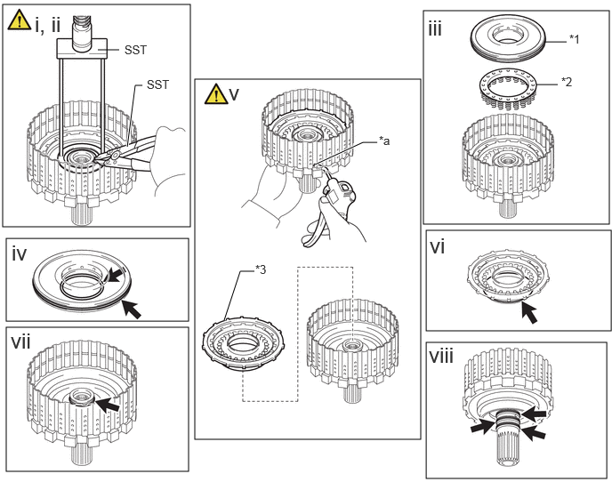
Hide 34638 63.REMOVE C-4 CLUTCH PISTON

a.
C456922C01
2.281,0.927 4.927,5.146 2.646,4.219 0.031,0.052 2.229,2.656 2.198,2.604 0.073,2.792 2.208,3.76 2.135,0.969 0.073,3.833 2.208,5.521 2.135,1.688 4.958,0.125 7.135,2.625 2.177,2.5 4.99,2.698 7.156,3.875 2.167,1.177 4.99,4.01 7.104,5.604 2.115,1.594 6.385,0.49 6.635,0.49 false 1.49,1.719 1.583,1 1.583,1 1.667,1 true 4.417,1.667 4.25,1.667 4.25,1.667 3.688,1.927 true 2.979,3.177 2.813,3.177 2.813,3.177 2.625,3.75 true 1.146,0.583 1.396,0.583 false 6.281,0.99 6.531,0.99 false 0.406,0.135 0.844,0.563 0.438,0.427 18 false i, ii 5.021,4.01 5.323,4.427 0.302,0.417 18 false viii 5.01,0.177 5.292,0.531 0.281,0.354 18 false iii 0.135,2.813 0.417,3.167 0.281,0.354 18 false iv 0.125,3.844 0.521,4.24 0.396,0.396 18 false vii 2.677,0.938 3.01,1.313 0.333,0.375 18 false v 5.031,2.729 5.365,3.104 0.333,0.375 18 false vi 1.458,0.5 1.917,0.698 0.458,0.198 10 false SST 1.719,0.906 2.177,1.104 0.458,0.198 10 false SST 4.438,1.563 4.75,1.76 0.313,0.198 10 false *a 2.99,3.073 3.219,3.333 0.229,0.26 10 false *3 6.667,0.375 6.896,0.635 0.229,0.26 10 false *1 6.573,0.875 6.802,1.135 0.229,0.26 10 false *2
*1 C-4 Clutch Balancer *2 Forward Clutch Return Spring Sub-assembly (C-4 clutch)
*3 C-4 Clutch Piston - -
*a Oil Hole - -


i.

Set SST on the C-4 clutch balancer and compress the forward clutch return spring sub-assembly (C-4 clutch) using a press.

SST
09387-00020  


ii.

Using SST, remove the snap ring from the output shaft assembly.

SST
09350-30020  (09350-07070)


iii.

Remove the C-4 clutch balancer and forward clutch return spring sub-assembly (C-4 clutch) from the output shaft assembly.


iv.

Remove the 2 O-rings from the C-4 clutch balancer.


v.

While holding the output shaft assembly, apply compressed air (400 kPa (4.1 kgf/cm2, 58 psi)) to the oil hole to remove the C-4 clutch piston from the output shaft assembly.


vi.

Remove the O-ring from the C-4 clutch piston.


vii.

Remove the O-ring from the output shaft assembly.


viii.

Remove the 3 clutch drum oil seal rings from the output shaft assembly.


Hide 35603A 64.INSPECT FORWARD CLUTCH RETURN SPRING SUB-ASSEMBLY (C-4 CLUTCH)

Z101186

Click here(Click here)

Hide 35639B 65.REMOVE BRAKE PLATE STOPPER SPRING
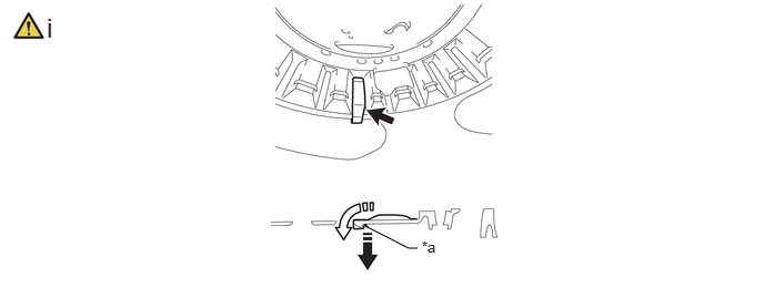
a.
C456923C01
3.427,2.125 3.833,2.333 3.833,2.333 3.917,2.333 false 3.958,2.24 4.271,2.396 0.313,0.156 10 false *a 0.438,0.115 0.74,0.552 0.302,0.438 18 false i
*a End of brake plate stopper spring - -
V113147

Pull lightly on the end
V113148

Remove in the direction of the arrow


i.

Remove the brake plate stopper spring.

1.

Pull lightly on the end of the brake plate stopper spring.

2.

Remove the brake plate stopper spring from the automatic transmission case sub-assembly in the direction indicated by the arrow.


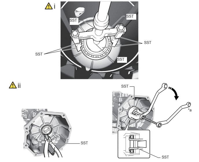
Hide 33111F 66.REMOVE TRANSMISSION CASE OIL SEAL
a.
C456924C01
2.865,0.552 3.333,0.25 3.333,0.25 3.417,0.25 true 2.333,1.677 2.5,1.667 2.5,1.667 3.219,1.125 true 2.042,1.563 2.5,1.76 0.458,0.198 10 false SST 3.458,0.167 3.917,0.365 0.458,0.198 10 false *1 0.385,0.052 0.969,0.906 0.583,0.854 18 false i
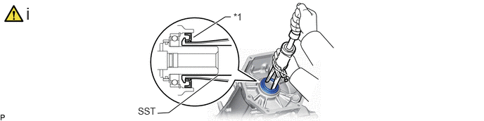
*1 Transmission Case Oil Seal - -


i.

Using SST, remove the transmission case oil seal from the automatic transmission case sub-assembly.

SST
09308-36010  

NOTICE:

When removing the transmission case oil seal, make sure not to damage the automatic transmission case sub-assembly.


Hide 36701C 67.REMOVE BALL BEARING

a.
C456983C01
1.844,5.167 2.875,5.167 true 4.667,3.115 4.833,3.115 4.833,3.115 4.833,3.865 true 3.677,1.719 5.125,1.563 5.125,1.563 4.302,1.333 true 3.917,1.083 4.417,0.583 4.417,0.583 4.5,0.583 true 2.833,0.75 3,0.75 3,0.75 3.5,1.083 true 2.792,1.719 1.583,1.948 1.583,1.948 2.76,1.573 true 3.438,1.583 4.063,2.177 4.063,2.177 4.146,2.177 true 4.938,5.333 5.698,5.677 5.698,5.677 5.781,5.677 true 1.938,0.073 2.219,0.427 0.281,0.354 18 false i 0.635,2.927 0.917,3.281 0.281,0.354 18 false ii 2.906,5.063 3.365,5.26 0.458,0.198 10 false SST 4.365,3.021 4.823,3.219 0.458,0.198 10 false SST 6.771,3.875 7.094,4.156 0.323,0.281 10 false *a 5.188,1.448 5.646,1.646 0.458,0.198 10 false SST 4.552,0.5 4.906,0.708 0.354,0.208 10 true SST 2.51,0.646 2.823,0.896 0.313,0.25 10 true SST 1.271,1.865 1.729,2.063 0.458,0.198 10 false SST 4.219,2.052 4.573,2.26 0.354,0.208 10 true SST 5.823,5.573 6.281,5.771 0.458,0.198 10 false SST
*a Hold - -
V113147

Turn - -


i.

for Inside:

1. Using SST, remove the ball bearing from the automatic transmission case sub-assembly.

SST
09950-40011  (09951-04020, 09952-04010, 09953-04030, 09955-04031, 09957-04010, 09954-04010)
09950-60011  (09951-00650)


ii.

for Outside:

1. Using SST, remove the snap ring from the automatic transmission case sub-assembly.

SST
09350-30020  (09350-07060)

2. Using SST, remove the ball bearing from the automatic transmission case sub-assembly.

SST
09612-65014  (09612-01060)


Hide 35141B 68.REMOVE AUTOMATIC TRANSMISSION CASE PLUG

HINT:

If automatic transmission fluid leaks from an automatic transmission case plug or the plug is corroded, replace it.

a.
C456925C01
0.427,0.094 0.969,0.469 0.542,0.375 18 false i - iii
V100135

for T55 "TORX"
V100136

for 12 mm head
V100137

for 24 mm head - -


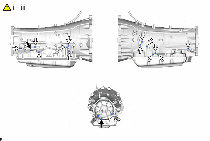
i.

for T55 "TORX":

1. Using a T55 "TORX" socket wrench, remove the 2 automatic transmission case plugs and 2 O-rings from the automatic transmission case sub-assembly.


ii.

for 12 mm head:

1. Remove the 13 automatic transmission case plugs and 13 O-rings from the automatic transmission case sub-assembly.


iii.

for 24 mm head:

1. Remove the 2 automatic transmission case plugs and 2 O-rings from the automatic transmission case sub-assembly.


Hide 35104 69.INSPECT AUTOMATIC TRANSMISSION CASE SUB-ASSEMBLY

Z101186

(Click here)