AJA0F AUTOMATIC TRANSMISSION / TRANSAXLE VALVE BODY ASSEMBLY INSTALLATION
CAUTION / NOTICE / HINT
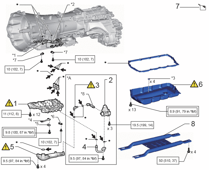
| Procedure | Part Name Code |

|

|

|
|
|---|---|---|---|---|---|
| 1 | TRANSMISSION VALVE BODY ASSEMBLY | 35400A | ( ) |
- | - |
| 2 | OIL PUMP WITH MOTOR ASSEMBLY | 35300D | - | - | - |
| 3 | NO. 3 TRANSMISSION OIL PIPE | 33129H | () |
- | - |
| 4 | NO. 2 TRANSMISSION OIL PIPE | 33129G | - | - | - |
| 5 | VALVE BODY OIL STRAINER ASSEMBLY | 35330 | () |
- | - |
| 6 | AUTOMATIC TRANSMISSION OIL PAN SUB-ASSEMBLY | 35106 | () |
- | - |
| 7 | ADD AUTOMATIC TRANSMISSION FLUID | - | - | () |
- |
| 8 | OIL PAN PROTECTOR ASSEMBLY | 51440 | - | - | - |
| *A | w/ Stop And Start System | - | - |
| *1 | NO. 1 ATF TEMPERATURE SENSOR | *2 | NO. 2 ATF TEMPERATURE SENSOR |
| *3 | TRANSMISSION OIL CLEANER MAGNET | *4 | MANUAL DETENT SPRING SUB-ASSEMBLY |
| *5 | MANUAL DETENT SPRING COVER | *6 | WIRE HARNESS CLAMP |
| *7 | LOCK PLATE | *8 | NO. 4 TRANSMISSION OIL PIPE |

|
Tightening torque for "Major areas involving basic vehicle performance such as moving/turning/stopping": N*m (kgf*cm, ft.*lbf) |

|
N*m (kgf*cm, ft.*lbf): Specified torque |
| ● | Non-reusable part |

|
Toyota Genuine ATF WS |
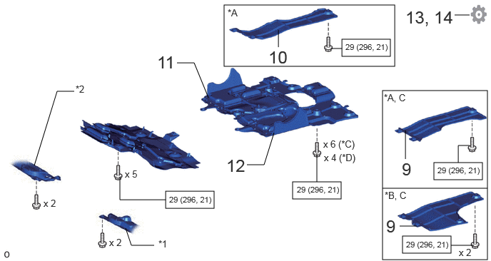
| Procedure | Part Name Code |
|
|
|
|
|---|---|---|---|---|---|
| 9 | FRAME UNDER COVER ASSEMBLY LH | 51450C | - | - | - |
| 10 | FRAME UNDER COVER ASSEMBLY RH | 51430A | - | - | - |
| 11 | NO. 2 ENGINE UNDER COVER ASSEMBLY | 51420 | - | - | - |
| 12 | NO. 1 ENGINE UNDER COVER ASSEMBLY | 51410 | - | - | - |
| 13 | PERFORM INITIALIZATION | - | - | - | () |
| 14 | CATALYST DETERIORATION CONFIRMATION DRIVING PATTERN | - | - | - | () |
| *A | for V35A-FTS | *B | for F33A-FTV |
| *C | w/ Cover | *D | w/o Cover |
| *1 | ENGINE SIDE COVER SUB-ASSEMBLY LH | *2 | ENGINE SIDE COVER SUB-ASSEMBLY RH |
|
|
N*m (kgf*cm, ft.*lbf): Specified torque | - | - |
PROCEDURE

 35400A 1.INSTALL TRANSMISSION VALVE BODY ASSEMBLY
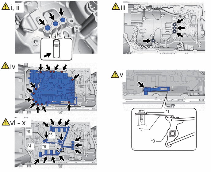
| *1 | Manual Detent Spring Cover | *2 | Manual Detent Spring Sub-assembly |
| *3 | Manual Valve Lever Sub-assembly | *4 | No. 1 ATF Temperature Sensor |
| *5 | No. 2 ATF Temperature Sensor | *6 | Lock Plate |
Coat 3 new brake drum gaskets with ATF.
Install the 3 brake drum gaskets to the automatic transmission case sub-assembly as shown in the illustration.
- NOTICE:
-
Install the steel pipe side facing the transmission valve body assembly side.
Coat 4 new gaskets with ATF and install them to the automatic transmission case sub-assembly.
Install the transmission valve body assembly to the automatic transmission case sub-assembly with the 12 bolts.
- Torque:
- 11 N*m (112 kgf*cm, 8 ft.*lbf)
- NOTICE:
-
Take care that the transmission wire does not become trapped.
Install the manual detent spring sub-assembly and manual detent spring cover to the automatic transmission case sub-assembly with the bolt.
- Torque:
- 9.8 N*m (100 kgf*cm, 87 in.*lbf)
Coat 2 new O-rings with the ATF and install it to the No. 1 ATF temperature sensor and No. 2 ATF temperature sensor.
Connect the No. 1 ATF temperature sensor and No. 2 ATF temperature sensor to the transmission valve body assembly with the 2 bolts and 2 lock plates.
- Torque:
- 10 N*m (102 kgf*cm, 7 ft.*lbf)
Install the wire harness clamp to the transmission valve body assembly with the bolt.
- Torque:
- 10 N*m (102 kgf*cm, 7 ft.*lbf)
Connect the transmission wire to the wire harness clamp.
Connect the 11 solenoid valve connectors.
35300D 2.INSTALL OIL PUMP WITH MOTOR ASSEMBLY (w/ Stop And Start System)
- Torque:
- 19.5 N*m (199 kgf*cm, 14 ft.*lbf)
33129H 3.INSTALL NO. 3 TRANSMISSION OIL PIPE (w/ Stop And Start System)
33129G 4.INSTALL NO. 2 TRANSMISSION OIL PIPE (w/ Stop And Start System)
35330 5.INSTALL VALVE BODY OIL STRAINER ASSEMBLY
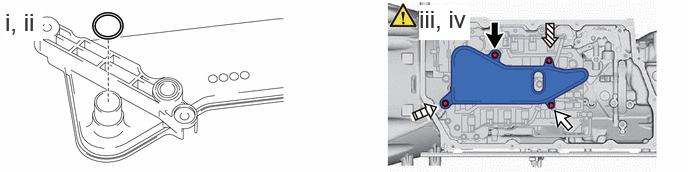
|
|
Bolt A |

|
Bolt B |

|
Bolt C |

|
Bolt D |
Coat a new O-ring with the ATF.
Install the O-ring to the valve body oil strainer assembly.
Temporarily install the valve body oil strainer assembly to the transmission valve body assembly with the 4 bolts.
Tighten the 4 bolts in the tightening order.
- Torque:
- 9.5 N*m (97 kgf*cm, 84 in.*lbf)
- HINT:
-
Tightening order: Temporarily install bolt A → Tighten bolt B → Tighten bolt C → Tighten bolt D → Tighten bolt A
35106 6.INSTALL AUTOMATIC TRANSMISSION OIL PAN SUB-ASSEMBLY
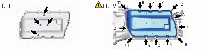
Install the 4 transmission oil cleaner magnets to the automatic transmission oil pan sub-assembly.
Install a new automatic transmission oil pan gasket to the automatic transmission oil pan sub-assembly.
Temporarily install the automatic transmission oil pan sub-assembly to the automatic transmission case sub-assembly with the 13 bolts.
Tighten the 13 bolts in the order shown in the illustration.
- Torque:
- 8.9 N*m (91 kgf*cm, 79 in.*lbf)
7.ADD AUTOMATIC TRANSMISSION FLUID
|
|
Click here() |
51440 8.INSTALL OIL PAN PROTECTOR ASSEMBLY
- Torque:
- 50 N*m (510 kgf*cm, 37 ft.*lbf)
51450C 9.INSTALL FRAME UNDER COVER ASSEMBLY LH (w/ Cover)
51430A 10.INSTALL FRAME UNDER COVER ASSEMBLY RH
51420 11.INSTALL NO. 2 ENGINE UNDER COVER ASSEMBLY
51410 12.INSTALL NO. 1 ENGINE UNDER COVER ASSEMBLY
13.PERFORM INITIALIZATION
14. CATALYST DETERIORATION CONFIRMATION DRIVING PATTERN (for V35A-FTS)
|
|
|