SEAT REAR NO. 1 SEAT ASSEMBLY(for 40/20/40 Split Seat Type RH Side) REMOVAL
CAUTION / NOTICE / HINT
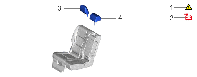
| Procedure | Part Name Code |

|

|

|
|
|---|---|---|---|---|---|
| 1 | PRECAUTION | - | ( ) |
- | - |
| 2 | DISCONNECT CABLE FROM NEGATIVE BATTERY TERMINAL | - | () |
- | - |
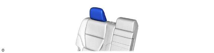
| 3 | NO. 1 SEAT HEADREST ASSEMBLY RH | 71940F | - | - | - |
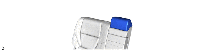
| 4 | REAR CENTER NO. 1 SEAT HEADREST ASSEMBLY | 71960G | - | - | - |
| *A | w/ Rear Seat Side Airbag | - | - |
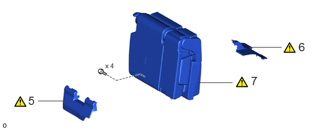
| Procedure | Part Name Code |
|
|
|
|
|---|---|---|---|---|---|
| 5 | REAR NO. 1 SEAT CUSHION HINGE COVER | 71691W | () |
- | - |
| 6 | REAR NO. 3 SEAT CUSHION HINGE COVER | 71692N | () |
- | - |
| 7 | REAR NO. 1 SEAT ASSEMBLY RH | - | () |
- | - |
CAUTION / NOTICE / HINT
The necessary procedures (adjustment, calibration, initialization or registration) that must be performed after parts are removed, installed or replaced during the rear No. 1 seat assembly RH removal/installation are shown below.
| Replaced Part or Performed Procedure | Necessary Procedures | Effect/Inoperative Function When Necessary Procedures are not Performed | Link |
|---|---|---|---|
| Disconnect cable from negative battery terminal | Memorize steering angle neutral point | Parking assist monitor system | () |
| Multi-terrain monitor system | () |
||
| Panoramic view monitor system | () |
- CAUTION:
-
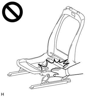
-
·
Wear protective gloves. Sharp areas on the parts may injure your hands.
·There is risk of injury.
- HINT:
-
·
When the cable is disconnected/reconnected to the battery terminal, systems temporarily stop operating. However, each system has a function that completes learning the first time the system is used.
-Learning completes when vehicle is driven
Effect/Inoperative Function When Necessary Procedures are not Performed Necessary Procedures Link Stop and start system Drive the vehicle until stop and start control is permitted (approximately 5 to 60 minutes) ( )Lighting system (EXT) Cornering lights Drive the vehicle straight ahead at 35 km/h (22 mph) or more for 5 seconds or more. ( )Pre-collision system Lane tracing assist system Lane departure alert system Adaptive high beam system
-Learning completes when vehicle is operated normally
Effect/Inoperative Function When Necessary Procedures are not Performed Necessary Procedures Link Power back door system Fully close the back door by hand.
- HINT:
-
Initialization is not necessary if the above procedures are performed while the back door is closed.
( )Air conditioning system After the ignition switch is turned to ON, the servo motor and expansion valve standard position is recognized. -
·Move both front seats to the frontmost position and fold them forward.
PROCEDURE

 1. PRECAUTION (w/ Rear Seat Side Airbag)
|
|
|
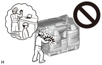
2.DISCONNECT CABLE FROM NEGATIVE BATTERY TERMINAL (w/ Rear Seat Side Airbag)
|
|
|
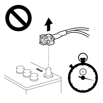
for 1GR-FE:
for F33A-FTV:
for V35A-FTS:
71940F 3.REMOVE NO. 1 SEAT HEADREST ASSEMBLY RH
71960G 4.REMOVE REAR CENTER NO. 1 SEAT HEADREST ASSEMBLY
71691W 5.REMOVE REAR NO. 1 SEAT CUSHION HINGE COVER
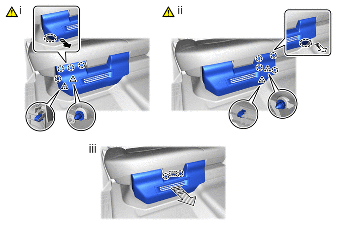

|
Place Hand Here |

|
Remove in this Direction (1) |

|
Remove in this Direction (2) |

|
Remove in this Direction (3) |
Place your hand at the position shown in the illustration and pull in the removal direction (1) to detach the clip and claw.
Place your hand at the position shown in the illustration and pull in the removal direction (2) to detach the clip and claw.
Pull in the removal direction (3) to detach the claw and guide to remove the rear No. 1 seat cushion hinge cover as shown in the illustration.
71692N 6.REMOVE REAR NO. 3 SEAT CUSHION HINGE COVER
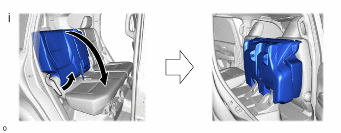
Operate the reclining adjuster release handle RH and fold down the rear No. 1 seat assembly RH.
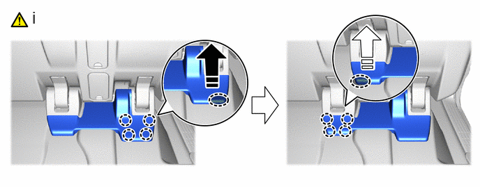
|
|
Place Hand Here |
|
Remove in this Direction (1) |
|
|
Remove in this Direction (2) | - | - |
Follow the procedure below to detach the claw.
1. Place your hand at the position shown in the illustration and pull in the removal direction (1) to detach the claw.
2. Place your hand at the position shown in the illustration and pull in the removal direction (2) to detach the claw.
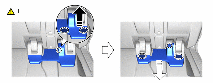
|
|
Place Hand Here |
|
Remove in this Direction (1) |
|
|
Remove in this Direction (2) | - | - |
Follow the procedure below to remove the rear No. 4 seat cushion hinge cover.
1. Place your hand at the position shown in the illustration and pull in the removal direction (1) to detach the claw.
2. Place your hand at the position shown in the illustration and pull in the removal direction (2) to detach the claw and remove the rear No. 3 seat cushion hinge cover.
7.REMOVE REAR NO. 1 SEAT ASSEMBLY RH
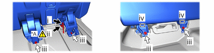
| *A | w/ Rear Seat Side Airbag | - | - |

|
Connector |

|
Bolt |
Disconnect the connector.
w/ Rear Seat Side Airbag:
1. Disconnect the connector of the rear No. 1 seat airbag assembly RH.
- NOTICE:
-
Do not pull while holding the wire harness.
- HINT:
-
Refer to How to Connect or Disconnect Airbag Connector: Click hereVehicle Interior>SUPPLEMENTAL RESTRAINT SYSTEMS>AIRBAG SYSTEM>HOW TO CONNECT OR DISCONNECT AIRBAG CONNECTOR
Remove the 4 bolts.
Pull out the 2 location pins of the rear No. 1 seat assembly RH.
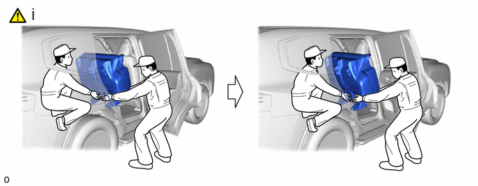
Remove and carry the rear No. 1 seat assembly RH out of the vehicle.
- NOTICE:
-
·
Protect the rear No. 1 seat legs.
·Carrying the rear No. 1 seat assembly RH from the vehicle must be performed by multiple people.
·Do not damage the rear No. 1 seat assembly RH, body exterior or interior parts.