HEATING / AIR CONDITIONING VISCOUS HEATER INSTALLATION
CAUTION / NOTICE / HINT
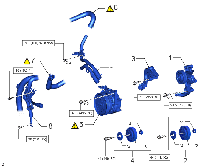
| Procedure | Part Name Code |

|

|

|
|
|---|---|---|---|---|---|
| 1 | NO. 2 IDLER PULLEY ASSEMBLY | 16630J | - | - | - |
| 2 | NO. 2 IDLER PULLEY SUB-ASSEMBLY | 16604C | - | - | - |
| 3 | IDLER PULLEY ASSEMBLY | 16630H | - | - | - |
| 4 | NO. 2 IDLER PULLEY SUB-ASSEMBLY | 16604C | - | - | - |
| 5 | VISCOUS HEATER WITH MAGNET CLUTCH ASSEMBLY | 87120G | ( ) |
- | - |
| 6 | REAR INLET HEATER WATER HOSE C | 87255C | () |
- | - |
| 7 | INLET HEATER WATER HOSE J | 87254J | () |
- | - |
| 8 | ENGINE WIRE | 82121 | - | - | - |
| *1 | HEATER WATER PIPE B | *2 | DUST COVER |
| *3 | IDLE PULLEY SUB-ASSEMBLY | *4 | IDLE PULLEY COLLAR |

|
Tightening torque for "Major areas involving basic vehicle performance such as moving/turning/stopping": N*m (kgf*cm, ft.*lbf) |

|
N*m (kgf*cm, ft.*lbf): Specified torque |
| Procedure | Part Name Code |
|
|
|
|
|---|---|---|---|---|---|
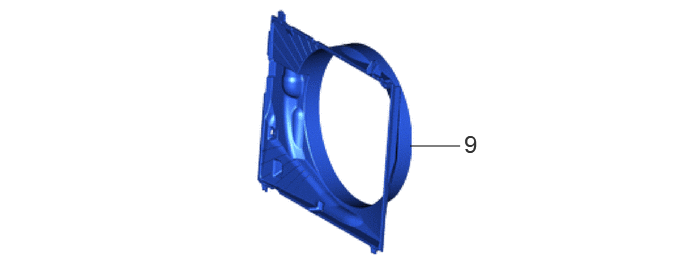
| 9 | FAN SHROUD | 16711 | - | - | - |
CAUTION / NOTICE / HINT
PROCEDURE

 16630J 1.INSTALL NO. 2 IDLER PULLEY ASSEMBLY
- Torque:
- 24.5 N*m (250 kgf*cm, 18 ft.*lbf)
16604C 2.INSTALL NO. 2 IDLER PULLEY SUB-ASSEMBLY
- Torque:
- 44 N*m (449 kgf*cm, 32 ft.*lbf)
16630H 3.INSTALL IDLER PULLEY ASSEMBLY
- Torque:
- 24.5 N*m (250 kgf*cm, 18 ft.*lbf)
16604C 4.INSTALL NO. 2 IDLER PULLEY SUB-ASSEMBLY
- Torque:
- 44 N*m (449 kgf*cm, 32 ft.*lbf)
87120G 5.INSTALL VISCOUS HEATER WITH MAGNET CLUTCH ASSEMBLY
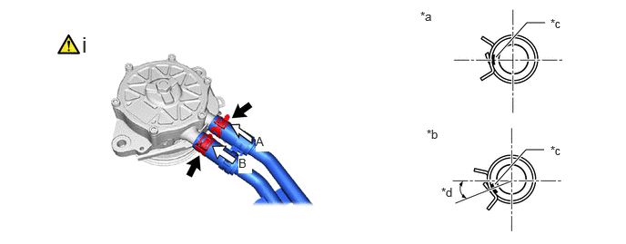
| *a | View A | *b | View B |
| *c | Marking | *d | Hose Clip Installation Angle (20°) |
Install the heater water pipe B and hose clip within the range shown in the illustration.
- NOTICE:
-
Do not apply excessive force to the heater water pipe B.
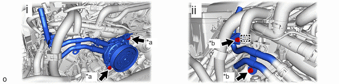
| *a | Bolt (A) | *b | Bolt (B) |
Install the viscous heater with magnet clutch assembly with the 2 bolts (A).
- Torque:
- 48.5 N*m (495 kgf*cm, 36 ft.*lbf)
Attach the guide and install the 2 bolts (B).
- Torque:
- 9.8 N*m (100 kgf*cm, 87 in.*lbf)
87255C 6.CONNECT REAR INLET HEATER WATER HOSE C
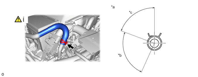
| *a | View A | *b | Rear Inlet Heater Water Hose C Installation Angle (75.7 to 95.7°) |
| *c | Hose Clip Installation Angle (40 to 100°) | - | - |
Connect the rear inlet heater water hose C and install the hose clip within the range shown in the illustration.
- NOTICE:
-
Do not apply excessive force to the rear inlet heater water hose C.
87245J 7.CONNECT INLET HEATER WATER HOSE J
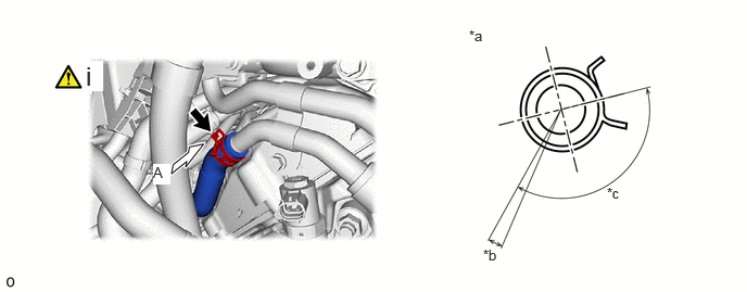
| *a | View A | *b | Inlet Heater Water Hose E Installation Angle (5.3°) |
| *c | Hose Clip Installation Angle (102.7 to 162.7°) | - | - |
Connect the inlet heater water hose J and install the hose clip within the range shown in the illustration.
- NOTICE:
-
Do not apply excessive force to the inlet heater water hose J.
82121 8.CONNECT ENGINE WIRE
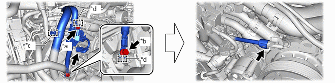
| *a | Bolt (A) | *b | Bolt (B) |
| *c | Clamp | *d | Guide |
- Torque:
- Bolt (A) : 10 N*m (102 kgf*cm, 7 ft.*lbf)
- Bolt (B) : 20 N*m (204 kgf*cm, 15 ft.*lbf)
16711 9.INSTALL FAN SHROUD