F33A-FTV ENGINE MECHANICAL CYLINDER BLOCK INSPECTION
PROCEDURE

 15708 1.INSPECT NO. 1 OIL NOZZLE SUB-ASSEMBLY AND NO. 2 OIL NOZZLE SUB-ASSEMBLY
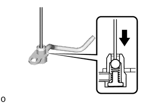
Push the check valve with a pin to check if it is stuck. If stuck, replace the No. 1 and No. 2 oil nozzle sub-assembly.
Push the check valve with a pin to check if it moves smoothly.
If the check valve does not move smoothly, clean or replace the No. 1 oil nozzle sub assembly or No. 2 oil nozzle sub-assembly.
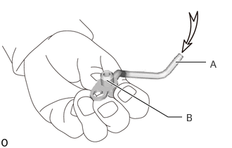

|
Air |
Apply air into A. Check that air does not leak through B.
If air leaks, clean or replace the No. 1 oil nozzle sub assembly or No. 2 oil nozzle sub-assembly.
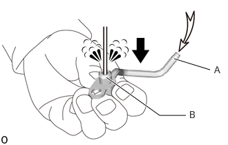

|
Push |
|
|
Air |
Push the check valve apply air into A. Check that air passes through B.
If air does not pass through B, clean or replace the No. 1 oil nozzle sub assembly or No. 2 oil nozzle sub-assembly.
11401 2.CLEAN CYLINDER BLOCK SUB-ASSEMBLY
Using a gasket scraper, remove all the gasket material from the top surface of the cylinder block sub-assembly.
Using a soft brush and solvent, thoroughly clean the cylinder block sub-assembly.
11401 3. VISUALLY CHECK CYLINDER BLOCK
Visually check the cylinder for vertical scratches.
If necessary, replace the cylinder block sub-assembly.
4.INSPECT CYLINDER BLOCK FOR WARPAGE
Using a precision straightedge and feeler gauge, measure the warpage of the surface where the cylinder head gasket contacts the cylinder head sub-assembly.
- Maximum Warpage:
-
0.05 mm (0.00197 in.)
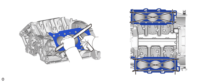
If the warpage is more than the maximum, replace the cylinder block sub-assembly.
5.INSPECT CYLINDER BORE
Using a cylinder gauge, measure the cylinder bore diameter at the positions (A) and (B) in the thrust and axial directions.
- Reference value (new parts):
-
86.000 to 86.013 mm (3.3858 to 3.3863 in.)
- Maximum Diameter:
-
86.03 mm (3.3870 in.)
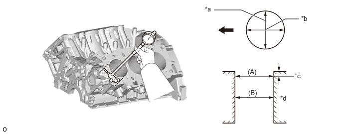
| *a | Thrust Direction | *b | Axial Direction |
| *c | 5 mm (0.197 in.) | *d | Center |
|
|
Engine Front | - | - |
If the diameter is more than the maximum, replace the cylinder block sub-assembly.
6.INSPECT PISTON DIAMETER
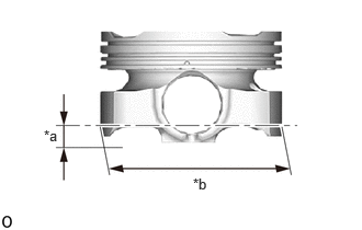
| *a | Distance |
| *b | Reference value |
Using a micrometer, measure the piston diameter at a right angle to the piston center line where the distance from the bottom of the piston is as specified.
- Distance:
-
7.3 mm (0.287 in.)
- Reference value (new parts):
-
85.948 to 85.966 mm (3.3838 to 3.3845 in.)
- Minimum Diameter:
-
85.925 mm (3.3829 in.)
7.INSPECT PISTON OIL CLEARANCE
Measure the cylinder bore diameter in the thrust direction.
Subtract the piston diameter measurement from the cylinder bore diameter measurement.
- Reference value (new parts):
-
0.034 to 0.065 mm (0.00134 to 0.00256 in.)
- Maximum Oil Clearance:
-
0.075 mm (0.00295 in.)
If the oil clearance is more than the maximum, replace all the pistons. If necessary, replace the cylinder block sub-assembly.
8.INSPECT RING GROOVE CLEARANCE
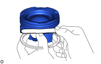
Using a feeler gauge, measure the clearance between a new piston ring set and the wall of the ring groove.
- Standard Ring Groove Clearance:
-
Item Specified Condition No. 1 compression ring 0.12 to 0.16 mm (0.00472 to 0.00630 in.) No. 2 compression ring 0.07 to 0.12 mm (0.00276 to 0.00472 in.) Oil ring 0.03 to 0.08 mm (0.00118 to 0.00315 in.)
If the clearance is not as specified, replace the piston.
9.INSPECT PISTON RING END GAP
Insert the piston ring into the cylinder bore.
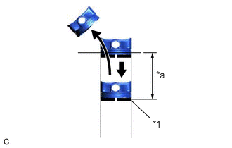
| *1 | Piston Ring |
| *a | 100 mm (3.937 in.) |
Using a piston, push in the piston ring slightly beyond the bottom of the ring travel, 100 mm (3.937 in.) from the top of the cylinder block sub-assembly.
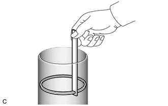
Using a feeler gauge, measure the end gap.
- Standard End Gap:
-
Item Specified Condition No. 1 compression ring 0.220 to 0.245 mm (0.00866 to 0.00965 in.) No. 2 compression ring 0.52 to 0.57 mm (0.0205 to 0.0224 in.) Oil ring 0.10 to 0.30 mm (0.00394 to 0.0118 in.)
- Maximum End Gap:
-
Item Specified Condition No. 1 compression ring 0.35 mm (0.0138 in.) No. 2 compression ring 0.70 mm (0.0276 in.) Oil ring 0.40mm (0.0157 in.)
If the end gap is more than the maximum, replace the piston ring. If the end gap is more than the maximum even with a new piston ring, replace the cylinder block sub-assembly.
10.INSPECT PISTON PIN OIL CLEARANCE
Check each mark on the piston, piston pin and connecting rod sub-assembly.
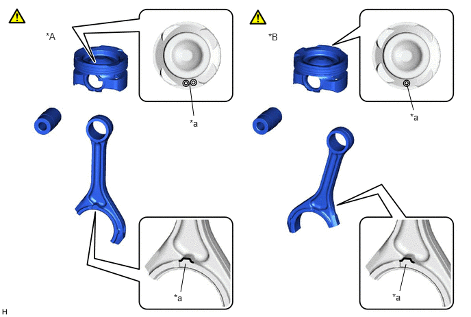
| *A | for Bank 1 (Piston RH) | *B | for Bank 2 (Piston LH) |
| *a | Front Mark | - | - |
- NOTICE:
-
Take care as the matchmark on the piston RH connecting rod is reversed for the piston LH.
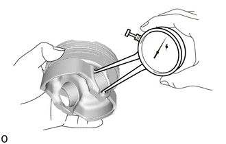
Using a caliper gauge, measure the inside diameter of the piston pin hole.
- Standard Piston Pin Hole Inside Diameter:
-
28.036 to 28.051 mm (1.1038 to 1.1044 in.)
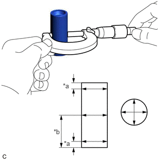
| *a | 5 mm (0.197 in.) |
| *b | 25 mm (0.984 in.) |
Using a micrometer, measure the piston pin diameter.
- Standard Piston Pin Diameter:
-
27.994 to 28.000 mm (1.1021 to 1.1024 in.)
Subtract the piston pin diameter measurement from the piston pin hole diameter measurement.
- Standard Oil Clearance:
-
0.036 to 0.057 mm (0.00142 to 0.00224 in.)
- Maximum Oil Clearance:
-
0.062 mm (0.00244 in.)
If the oil clearance is more than the maximum, replace the piston and piston pin as a set.
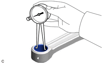
Using a caliper gauge, measure the inside diameter of the connecting rod small end bush.
- Standard Bushing Inside Diameter:
-
28.036 to 28.048 mm (1.1038 to 1.1042 in.)
Subtract the piston pin diameter measurement from the bushing inside diameter measurement.
- Standard Oil Clearance:
-
0.036 to 0.054 mm (0.00142 to 0.00213 in.)
- Maximum Oil Clearance:
-
0.059 mm (0.00232 in.)
- NOTICE:
-
Take care as the matchmark on the piston RH connecting rod is reversed for the piston LH.
- HINT:
-
·
If the oil clearance is more than the maximum, replace the connecting rod sub-assembly.
·If necessary, replace the connecting rod sub-assembly and piston sub-assembly with pin.
13201 11.INSPECT CONNECTING ROD SUB-ASSEMBLY
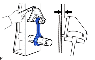
Using a rod aligner and feeler gauge, check the connecting rod sub-assembly alignment.
Check for bend.
- Maximum bend:
-
0.05 mm (0.00197 in.) per 100 mm (3.94 in.)
If the bend is more than the maximum, replace the connecting rod sub-assembly.
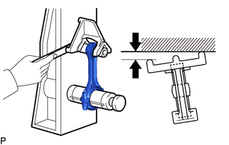
Check for twist.
- Maximum twist:
-
0.15 mm (0.00591 in.) per 100 mm (3.94 in.)
If the twist is more than the maximum, replace the connecting rod sub-assembly.
13265 12.INSPECT CONNECTING ROD BOLT
Using a vernier caliper, measure the tension portion diameter of the connecting rod bolt.

| *a | Tension Portion | - | - |
- Standard diameter:
-
9.0 to 9.1 mm (0.354 to 0.358 in.)
- Minimum diameter:
-
8.6 mm (0.339 in.)
If the diameter is less than the minimum, replace the connecting rod bolt.
- HINT:
-
A connecting rod bolt can be reused up to 10 times.
13601A 13.INSPECT NO.1 BALANCESHAFT SUB-ASSEMBLY
Inspect the diameter of the journals.
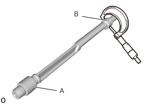
Using a micrometer, measure the diameter of the balanceshaft main journals.
| Item | Specified Condition |
|---|---|
| A | 29.941 to 29.960 mm (1.1788 to 1.1795 in.) |
| B | 27.541 to 27.560 mm (1.0843 to 1.0850 in.) |
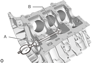
Inspect the diameter of the bearings.
Using a cylinder gauge, measure the inside diameter of the balanceshaft bearings.
| Item | Specified Condition |
|---|---|
| A | 30.000 to 30.020 mm (1.1811 to 1.1819 in.) |
| B | 27.600 to 27.620 mm (1.0866 to 1.0874 in.) |
Inspect the oil clearance.
Subtract the balanceshaft main journal diameter measurement from the balanceshaft bearing inside diameter measurement.
- Standard Oil Clearance:
-
0.040 to 0.079 mm (0.00157 to 0.00311 in.)
- Maximum oil clearance:
-
0.15 mm (0.00591 in.)
If the oil clearance is more than the maximum, replace the cylinder block and balanceshaft.
13411 14.INSPECT CRANKSHAFT
Inspect for runout.
Clean the crank journal.
Place the crankshaft on V-blocks.
Using a dial indicator, measure the runout at the center of each journal.
- Maximum Runout:
-
0.04 mm (0.00158 in.)
If the runout is more than the maximum, replace the crankshaft.
Inspect the main journals.
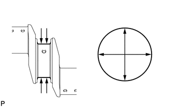
Using a micrometer, measure the diameter of each main journal.
- Standard Journal Diameter:
-
74.982 to 75.000 mm (2.9520 to 2.9528 in.)
If the diameter is not as specified, check the oil clearance. If necessary, replace the crankshaft.
Check each main journal for taper and out-of-round as shown in the illustration.
- Maximum Taper and Out-of-round:
-
0.01 mm (0.000394 in.)
If the taper or out-of-round is more than the maximum, replace the crankshaft.
Inspect the crank pins.
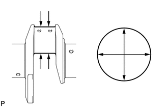
Using a micrometer, measure the diameter of each crank pin.
- Standard Crank Pin Diameter:
-
59.982 to 60.000 mm (2.3615 to 2.3622 in.)
If the diameter is not as specified, check the oil clearance. If necessary, replace the crankshaft.
Check each crank pin for taper and out-of-round as shown in the illustration.
- Maximum Taper and Out-of-round:
-
0.01 mm (0.000394 in.)
If the taper or out-of-round is more than the maximum, replace the crankshaft.
15.INSPECT CRANKSHAFT OIL CLEARANCE
- HINT:
-
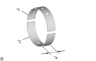 1.031,0.552 0.771,0.385 true 1.073,1.313 0.813,1.427 true 1.927,1.979 2.24,2.135 0.313,0.156 10 false *a 0.583,0.271 0.896,0.427 0.313,0.156 10 false *1 0.625,1.406 0.938,1.604 0.313,0.198 10 false *2
*1 No. 1 and No. 2 Crankshaft Bearings *2 No. 3 and No. 4 Crankshaft Bearings *a 20.3 mm (0.799 in.)
-
Main bearings come in widths of 20.3 mm (0.799 in.)
Clean each main journal and bearing.
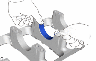
Install the crankshaft bearings.
Click hereEngine / Hybrid System>F33A-FTV (ENGINE MECHANICAL)>CYLINDER BLOCK>REASSEMBLY
Install the upper crankshaft thrust washers.
Click hereEngine / Hybrid System>F33A-FTV (ENGINE MECHANICAL)>CYLINDER BLOCK>REASSEMBLY
Place the crankshaft on the cylinder block sub-assembly.
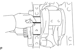
| *a | Plastigage |
Lay a strip of Plastigage across each journal.
Install the crankshaft bearing caps.
- NOTICE:
-
Do not turn the crankshaft.
Click hereEngine / Hybrid System>F33A-FTV (ENGINE MECHANICAL)>CYLINDER BLOCK>REASSEMBLY
Remove the crankshaft bearing caps.
Click hereEngine / Hybrid System>F33A-FTV (ENGINE MECHANICAL)>CYLINDER BLOCK>DISASSEMBLY
Measure the Plastigage at its widest point.
- Standard Oil Clearance:
-
0.038 to 0.062 mm (0.00150 to 0.00244 in.)
- Maximum Oil Clearance:
-
0.072 mm ( 0.00283 in.)
- NOTICE:
-
Remove the Plastigage completely after the measurement.
If the oil clearance is more than the maximum, replace the crankshaft bearing. If necessary, replace the crankshaft.
If replacing a crankshaft bearing, select a new one with the same number. If the number of the crankshaft bearing cannot be determined, calculate the correct crankshaft bearing number by adding together the numbers imprinted on the cylinder block sub-assembly and crankshaft. Then refer to the following table for the appropriate crankshaft bearing number. There are 5 sizes of standard bearings, marked "1", "2", "3", "4" or "5" accordingly.
EXAMPLE:
Cylinder block main journal bore diameter "1" (A) + Crankshaft main journal diameter "2" (B) = Total number 3 (use bearing "3" (C))
| Cylinder Block (A) | Crankshaft (B) | Use Bearing (C) |
|---|---|---|
| 1 | 0 | 1 |
| 1 | 2 | |
| 2 | 3 | |
| 2 | 0 | 2 |
| 1 | 3 | |
| 2 | 4 | |
| 3 | 0 | 3 |
| 1 | 4 | |
| 2 | 5 |
| Item | Specified Condition |
|---|---|
| Mark 1 | 79.000 to 79.006 mm (3.1102 to 3.1105 in.) |
| Mark 2 | 79.007 to 79.012 mm (3.1105 to 3.1107 in.) |
| Mark 3 | 79.013 to 79.018 mm (3.1107 to 3.1109 in.) |
| Item | Specified Condition |
|---|---|
| Mark 0 | 74.995 to 75.000 mm (2.9526 to 2.9528 in.) |
| Mark 1 | 74.989 to 74.994 mm (2.9523 to 2.9525 in.) |
| Mark 2 | 74.982 to 74.988 mm (2.9520 to 2.9523 in.) |
| Item | Specified Condition |
|---|---|
| Mark 1 | 1.982 to 1.984 mm (0.0780 to 0.0781 in.) |
| Mark 2 | 1.985 to 1.987 mm (0.0781 to 0.0782 in.) |
| Mark 3 | 1.988 to 1.990 mm (0.07827 to 0.07835 in.) |
| Mark 4 | 1.991 to 1.993 mm (0.0784 to 0.0785 in.) |
| Mark 5 | 1.994 to 1.996 mm (0.0785 to 0.0786 in.) |
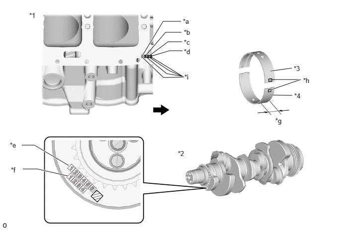
| *1 | Cylinder Block Sub-assembly | *2 | Crankshaft |
| *3 | No. 1 and No. 2 Crankshaft Bearings | *4 | No. 3 and No. 4 Crankshaft Bearings |
| *a | No. 4 Journal | *b | No. 3 Journal |
| *c | No. 2 Journal | *d | No. 1 Journal |
| *e | Crank Pin Diameter Mark | *f | Crankshaft Main Journal Diameter Mark |
| *g | 20.3 mm (0.799 in.) | *h | Crankshaft Bearing Code |
| *i | Cylinder Block Journal Code | - | - |
|
|
Engine Front | - | - |
11581 16.INSPECT CRANKSHAFT BEARING CAP BOLT
Using a vernier caliper, measure the tension portion diameter of bolt A and B.
| Item | Specified Condition |
|---|---|
| Bolt A | 106 mm (4.17 in.) |
| Bolt B | 90.5 mm (3.56 in.) |
| Item | Specified Condition |
|---|---|
| Bolt A | 73 mm (2.87 in.) |
| Bolt B | 63 mm (2.48 in.) |
- Standard diameter:
- for bolt A:
-
10.8 to 11.0 mm (0.425 to 0.433 in.)
- for bolt B:
-
9.8 to 10.0 mm (0.386 to 0.394 in.)
- Minimum diameter:
- for bolt A:
-
10.5 mm (0.413 in.)
- for bolt B:
-
9.5 mm (0.374 in.)
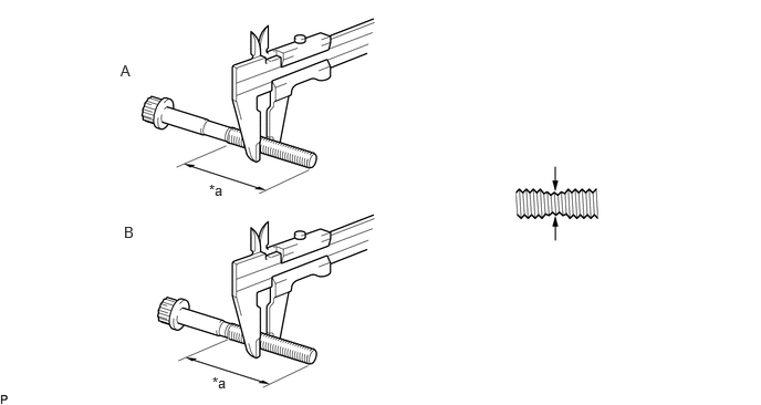
| *a | Measuring Area | - | - |
- HINT:
-
If a visual check reveals no excessively thin areas, check the center of the crankshaft bearing cap bolt (see illustration) and find the area that has the lowest diameter.
If the diameter is less than the minimum, replace the crankshaft bearing cap bolt.