F33A-FTV ENGINE MECHANICAL CYLINDER BLOCK REASSEMBLY
CAUTION / NOTICE / HINT
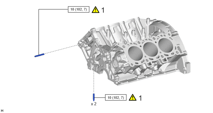
| Procedure | Part Name Code |

|

|

|
|
|---|---|---|---|---|---|
| 1 | STUD BOLT | - | ( ) |
- | - |

|
N*m (kgf*cm, ft.*lbf): Specified torque | - | - |
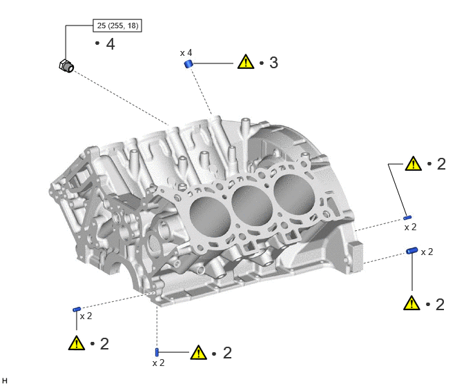
| Procedure | Part Name Code |
|
|
|
|
|---|---|---|---|---|---|
| 2 | STRAIGHT PIN | - | () |
- | - |
| 3 | RING PIN | - | () |
- | - |
| 4 | CYLINDER BLOCK WATER DRAIN COCK PLUG | 11415A | () |
- | - |
|
|
N*m (kgf*cm, ft.*lbf): Specified torque | ● | Non-reusable part |
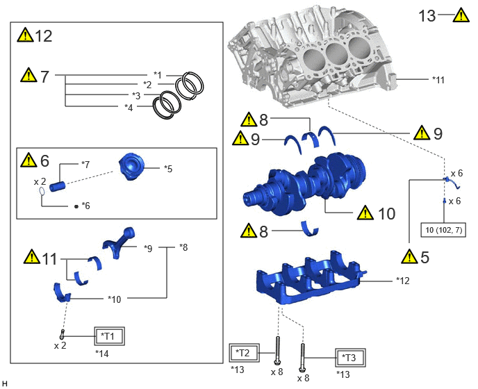
| Procedure | Part Name Code |
|
|
|
|
|---|---|---|---|---|---|
| 5 | NO. 1 OIL NOZZLE SUB-ASSEMBLY AND NO. 2 OIL NOZZLE SUB-ASSEMBLY | 15708 | () |
- | - |
| 6 | PISTON SUB-ASSEMBLY WITH PIN | - | () |
- | - |
| 7 | PISTON RING SET | 13011 | () |
- | - |
| 8 | CRANKSHAFT BEARING | - | () |
- | - |
| 9 | UPPER CRANKSHAFT THRUST WASHER | 11791 | () |
- | - |
| 10 | CRANKSHAFT | 13411 | () |
- | - |
| 11 | CONNECTING ROD BEARING | 13041 | () |
- | - |
| 12 | PISTON SUB-ASSEMBLY WITH CONNECTING ROD | - | () |
- | - |
| 13 | INSPECT CONNECTING ROD THRUST CLEARANCE | - | () |
- | - |
| *1 | NO. 1 COMPRESSION RING | *2 | NO. 2 COMPRESSION RING |
| *3 | OIL RING RAIL | *4 | OIL RING EXPANDER |
| *5 | PISTON | *6 | PISTON PIN HOLE SNAP RING |
| *7 | PISTON PIN | *8 | CONNECTING ROD SUB-ASSEMBLY |
| *9 | CONNECTING ROD | *10 | CONNECTING ROD CAP |
| *11 | CYLINDER BLOCK SUB-ASSEMBLY | *12 | CRANKSHAFT BEARING CAP SUB-ASSEMBLY |
| *13 | CRANKSHAFT BEARING CAP BOLT | *14 | CONNECTING ROD BOLT |

|
Tightening torque for "Major areas involving basic vehicle performance such as moving/turning/stopping": N*m (kgf*cm, ft.*lbf) |
|
N*m (kgf*cm, ft.*lbf): Specified torque |
| ● | Non-reusable part | - | - |
| *T1 | 1st: 50 (510, 37) 2nd: Turn 90° |
*T2 | 1st: 35 (357, 26) 2nd: Turn 90° 3rd: Turn 90° |
| *T3 | 1st: 60 (612, 44) 2nd: Turn 90° |
- | - |
CAUTION / NOTICE / HINT
- HINT:
-
Perform "Inspection After Repairs" after replacing the piston or piston ring.
-
Click hereEngine / Hybrid System>F33A-FTV (ENGINE CONTROL)>ECD SYSTEM (w/ DPF)>INITIALIZATION
PROCEDURE

 1.INSTALL STUD BOLT
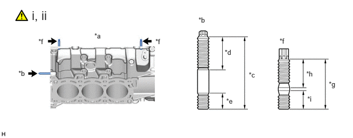
| *a | for Bank 1 | *b | Stud bolt A |
| *c | 55 mm (2.17 in.) | *d | 25 mm (0.984 in.) |
| *e | 12 mm (0.472 in.) | *f | Stud bolt A |
| *g | 35 mm (1.39 in.) | *h | 20 mm (0.787 in.) |
| *i | 13 mm (0.512 in.) | - | - |
Using E7 "TORX" socket wrench, install the stud bolts A.
- Torque:
- 10 N*m (102 kgf*cm, 89 in.*lbf)
Using E8 "TORX" socket wrench, install the stud bolts B.
- Torque:
- 10 N*m (102 kgf*cm, 89 in.*lbf)
2.INSTALL STRAIGHT PIN
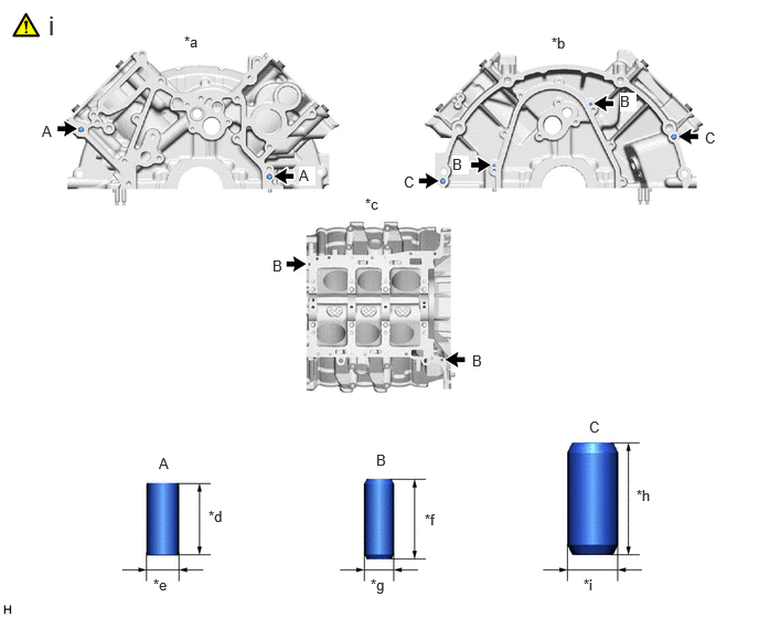
| *a | Front Side | *b | Rear Side |
| *c | Cylinder Block Sub-assembly Lower Side | *d | 15 mm (0.591 in.) |
| *e | 8 mm (0.315 in.) | *f | 16 mm (0.630 in.) |
| *g | 6 mm (0.236 in.) | *h | 22 mm (0.866 in.) |
| *i | 10 mm (0.394 in.) | - | - |
Using a plastic-faced hammer, tap in new straight pins to the cylinder block sub-assembly.
- Standard Protrusion Height:
-
Item Specified Condition A 6.5 to 8.5 mm (0.256 to 0.335 in.) B 4.0 to 6.0 mm (0.158 to 0.236 in.) C 10.0 to 12.0 mm (0.393 to 0.472 in.)
3.INSTALL RING PIN
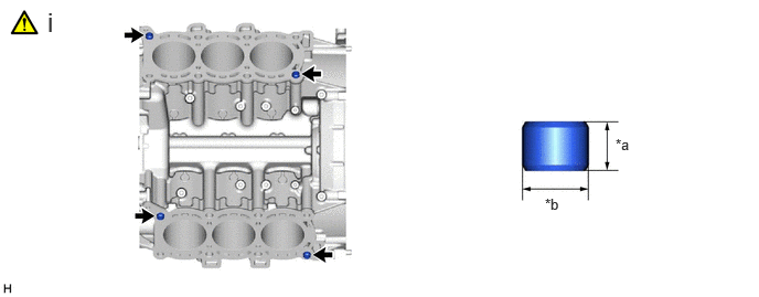
| *a | 11 mm (0.433 in.) | *b | 15 mm (0.591 in.) |
Using a plastic-faced hammer, tap in new ring pins to the cylinder block sub-assembly.
- Standard Protrusion Height:
- 5.5 to 7.5 mm (0.217 to 0.295 in.):
11415A 4.INSTALL CYLINDER BLOCK WATER DRAIN COCK PLUG
- Torque:
- 25 N*m (255 kgf*cm, 18 ft.*lbf)
5.INSTALL NO. 1 OIL NOZZLE SUB-ASSEMBLY AND NO. 2 OIL NOZZLE SUB-ASSEMBLY
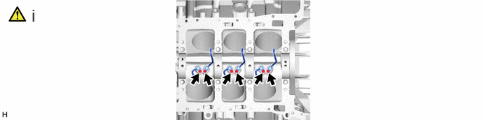
Using a 5 mm hexagon wrench, install the No. 1 oil nozzle sub-assemblies and No. 2 oil nozzle sub-assemblies with the 6 bolts.
- Torque:
- 10 N*m (102 kgf*cm, 7 ft.*lbf)
6.INSTALL PISTON SUB-ASSEMBLY WITH PIN
|
|
|
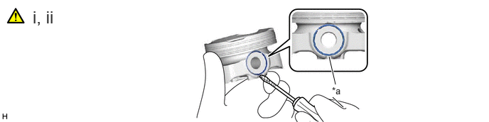
| *a | Cutout Portion | - | - |
Using a screwdriver, install a new piston pin hole snap ring at one end of the piston pin hole.
- HINT:
-
Confirm that the end gap of the snap ring is not aligned with the pin hole cutout portion of the piston.
- HINT:
-
·
The piston and piston pin are a matched set.
·Confirm that the end gap of the snap ring is not aligned with the pin hole cutout portion of the piston.
Coat the piston pin with engine oil.
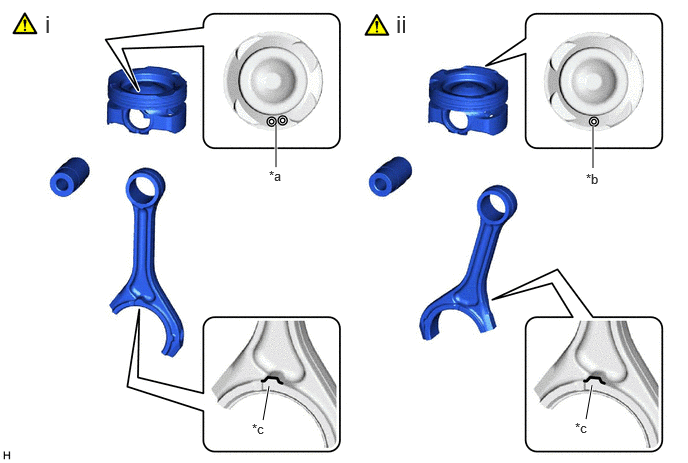
| *a | Piston Matchmark (Piston RH) | *b | Piston Matchmark (Piston LH) |
| *c | Piston Matchmark (Connecting Rod) | - | - |
for Bank 1:
Align the piston matchmark of the piston and connecting rod, and push in the piston pin with your thumb.
- HINT:
-
·
The piston and pin are a matched set.
·Take care as the matchmark on the connecting rod side of the piston RH is reversed from the piston LH.
·Check the fitting condition between the piston and piston pin by trying to move the piston back and forth on the piston pin.
for Bank 2:
Align the piston matchmark of the piston and connecting rod, and push in the piston pin with your thumb.
- HINT:
-
·
The piston and pin are a matched set.
·Take care as the matchmark on the connecting rod side of the piston LH is reversed from the piston RH.
·Check the fitting condition between the piston and piston pin by trying to move the piston back and forth on the piston pin.
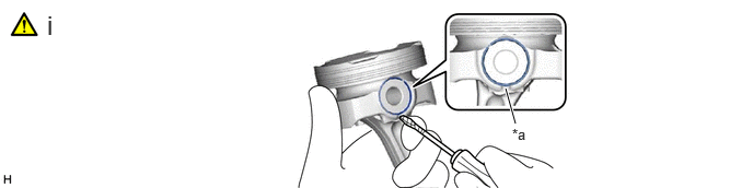
| *a | Cutout Portion | - | - |
Using a screwdriver, install a new piston pin hole snap ring at the other end of the piston pin hole.
- HINT:
-
Confirm that the end gap of the snap ring is not aligned with the pin hole cutout portion of the piston.
13011 7.INSTALL PISTON RING SET
|
|
|
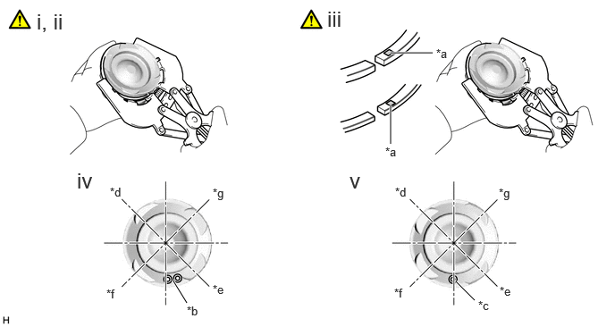
| *a | Code Mark | *b | Piston Matchmark (Piston RH) |
| *c | Piston Matchmark (Piston LH) | *d | No. 1 Compression Ring End Gap Position |
| *e | No. 2 Compression Ring End Gap Position | *f | Oil Ring Rail End Gap Position |
| *g | Oil Ring Expander End Gap Position | - | - |
Install the oil ring expander by hand.
Using a piston ring expander, install the oil ring rail.
Using a piston ring expander, install the 2 compression rings so that the code marks are positioned as shown in the illustration.
- HINT:
-
·
Install the No. 1 compression ring with the code mark (1T) facing upward.
·Install the No. 2 compression ring with the code mark (2T) facing upward.
Position the piston rings so that the ring ends are as shown in the illustration. (Piston RH)
- NOTICE:
-
Do not align the ring ends.
Position the piston rings so that the ring ends are as shown in the illustration. (Piston LH)
- NOTICE:
-
Do not align the ring ends.
8.INSTALL CRANKSHAFT BEARING
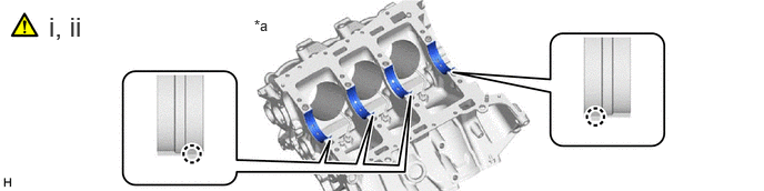
| *a | Cylinder Block Sub-assembly Side | - | - |
Clean and degrease the crankshaft main journal and the crankshaft bearing inner and outer surfaces.
- NOTICE:
-
Do not apply engine oil to the crankshaft bearing installation surface of the cylinder block and the back surface of the bearing.
Align the claw of the crankshaft bearing with the claw groove of the cylinder block, and install the crankshaft bearing.
- HINT:
-
Check that the oil hole of the cylinder block matches the oil hole of the crankshaft bearing.
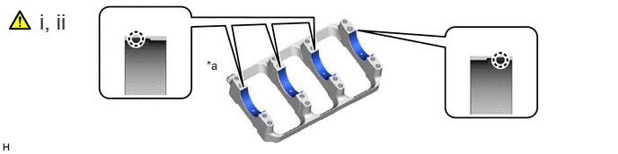
| *a | Crankshaft Bearing Cap Sub-assembly Side | - | - |
Clean and degrease the crankshaft bearing cap sub-assembly and the crankshaft bearing inner and outer surfaces.
- NOTICE:
-
Do not apply engine oil to the crankshaft bearing installation surface of the crankshaft bearing cap sub-assembly and the back surface of the bearing.
Align the claw of the crankshaft bearing with the claw groove of the crankshaft bearing cap sub-assembly, and install the crankshaft bearing.
11791 9.INSTALL UPPER CRANKSHAFT THRUST WASHER
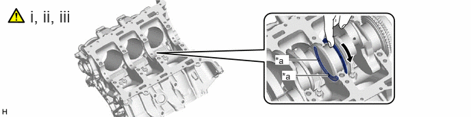
| *a | Oil Grooves | - | - |
Apply engine oil to the surface of the upper crankshaft bearing and the surface of the crankshaft journal, and install the crankshaft.
Apply engine oil to the upper crankshaft thrust washer.
Install the upper crankshaft thrust washers under the No. 3 journal position of the cylinder block sub-assembly with the oil grooves facing outward.
- HINT:
-
Push the crankshaft forward and backward on the cylinder block to increase the gap of the upper crankshaft thrust washer installation area, and install the crankshaft to the cylinder block.
- NOTICE:
-
Check that the upper crankshaft thrust washer is installed properly.
13411 10.INSTALL CRANKSHAFT
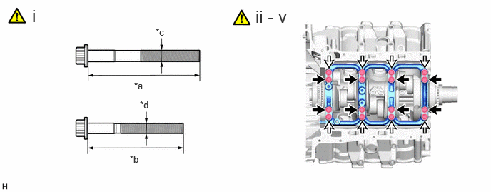
| *a | 106 mm (4.17 in.) (Crankshaft Bearing Cap Bolt A) | *b | 90.5 mm (3.56 in.) (Crankshaft Bearing Cap Bolt B) |
| *c | 10.5 mm (0.413 in.) or Less (Crankshaft Bearing Cap Bolt A Threaded Portion Minimum Diameter) | *d | 9.5 mm (0.374 in.) or Less (Crankshaft Bearing Cap Bolt B Threaded Portion Minimum Diameter) |

|
Crankshaft Bearing Cap Bolt A |

|
Crankshaft Bearing Cap Bolt B |
If the minimum diameter of the threaded portion is the value indicated in the illustration, replace the crankshaft bearing cap bolt with a new one.
- HINT:
-
A crankshaft bearing cap bolt can be reused up to 10 times.
Apply engine oil to the surface of the lower crankshaft bearing.
Temporarily place the crankshaft bearing cap sub-assembly to the cylinder block.
Using a plastic-faced hammer, lightly tap the crankshaft bearing cap sub-assembly to securely insert it.
Apply engine oil to the threads and beneath the head of the crankshaft bearing cap bolts, and install the 16 crankshaft bearing cap bolts.
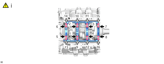
|
|
Crankshaft Bearing Cap Bolt A |
|
Crankshaft Bearing Cap Bolt B |
Temporarily install in 2 or 3 steps in the order shown in the illustration and tighten to the specified torque.
- Torque:
- Crankshaft Bearing Cap Bolt A : 35 N*m (357 kgf*cm, 26 ft.*lbf)
- Crankshaft Bearing Cap Bolt B : 60 N*m (612 kgf*cm, 44 ft.*lbf)
- NOTICE:
-
Tighten the bolts while checking that the crankshaft rotates smoothly.
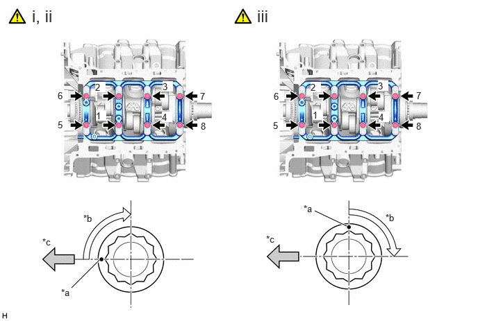
| *a | Painted Mark | *b | 90° |
| *c | Front Side | - | - |
|
|
Crankshaft Bearing Cap Bolt A | - | - |
Mark the front side of the crankshaft bearing cap bolts A with paint.
Tighten the crankshaft bearing cap bolts A 90° in the sequence as shown in the llustration.
- NOTICE:
-
Tighten the bolts while checking that the crankshaft rotates smoothly.
Tighten the crankshaft bearing cap bolts A 90° in the sequence as shown in the llustration.
- NOTICE:
-
Tighten the bolts while checking that the crankshaft rotates smoothly.
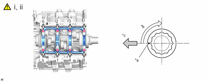
| *a | Painted Mark | *b | 90° |
| *c | Front Side | - | - |
|
|
Crankshaft Bearing Cap Bolt B | - | - |
Mark the front side of the crankshaft bearing cap bolts B with paint.
Tighten the crankshaft bearing cap bolts B 90° in the sequence as shown in the llustration.
- NOTICE:
-
Tighten the bolts while checking that the crankshaft rotates smoothly.
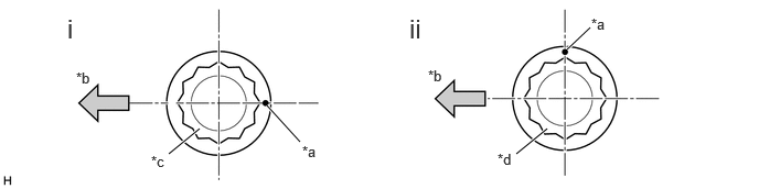
| *a | Painted Mark | *b | Front Side |
| *c | Crankshaft Bearing Cap Bolt A | *d | Crankshaft Bearing Cap Bolt B |
Check that the painted marks of crankshaft bearing cap bolts A are now at a 180° angle to the front.
Check that the painted marks of crankshaft bearing cap bolts B are now at a 90° angle to the front.
13041 11.INSTALL CONNECTING ROD BEARING
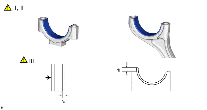
| *a | 1.8 to 2.4 mm (0.0709 to 0.0945 in.) | *b | 3.0 mm (0.118 in.) or less |
|
|
Matchmark on Connecting Rod Side | - | - |
Clean and degrease the connecting rod, the connecting rod bearing cap and the connecting rod bearing inner and outer surfaces.
- NOTICE:
-
Air blow the cracking fractured surface to remove foreign matter from the connecting rod and connecting rod bearing cap.
Install the connecting rod bearing to the connecting rod and bearing cap.
- NOTICE:
-
Do not apply engine oil to the connecting rod bearing installation surface of the connecting rod and the connecting rod bearing cap and to the back surface of the connecting rod bearing.
Using a vernier caliper, check that the connecting rod bearing is within the range shown in the illustration.
- HINT:
-
·
Check the range on the opposite side of the connecting rod side matchmark.
·Either is acceptable for the projecting side (3.0 mm (0.118 in.) or less).
12.INSTALL PISTON SUB-ASSEMBLY WITH CONNECTING ROD
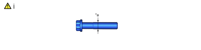
| *a | 8.6 mm (0.337 in.) or less | - | - |
If the minimum diameter of the threaded portion is the value indicated in the illustration, replace the connecting rod bolt with a new one.
- HINT:
-
A connecting rod bolt can be reused up to 10 times.
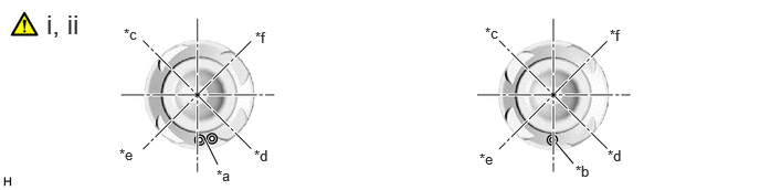
| *a | Piston Matchmark (Piston RH) | *b | Piston Matchmark (Piston LH) |
| *c | No. 1 Compression Ring End Gap Position | *d | No. 2 Compression Ring End Gap Position |
| *e | Oil Ring Rail End Gap Position | *f | Oil Ring Expander End Gap Position |
Apply engine oil to the cylinder walls, the pistons, and the surfaces of the connecting rod bearings.
Position the piston rings so that the ring ends are as shown in the illustration.
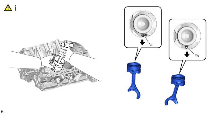
| *a | Piston Matchmark (Piston RH) | *b | Piston Matchmark (Piston LH) |
|
|
Engine Front | - | - |
Using a piston ring compressor, push the correctly numbered piston and connecting rod sub-assembly into the cylinder with the piston matchmark of the piston facing forward.
- NOTICE:
-
·
Take care as the matchmark on the connecting rod side of the piston LH is reversed from the engine front side.
·When inserting the piston sub-assembly with connecting rod, install it so that the connecting rod does not damage the wall of the cylinder and crank pin.
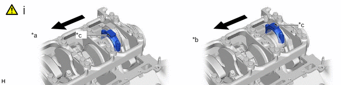
| *a | for Bank 1 (Piston RH) | *b | for Bank 2 (Piston LH) |
| *c | Piston Matchmark | - | - |
|
|
Engine Front | - | - |
Check the combinations of connecting rods and connecting rod caps and piston matchmark on connecting rod caps, and install the connecting rod caps to the connecting rods.
- NOTICE:
-
·
Take care as the matchmark on the connecting rod cap of the piston RH is reversed from the piston LH.
·Set the connecting rods and connecting rod caps in the same combinations as at disassembly.
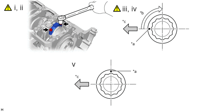
| *a | Painted Mark | *b | 90° |
| *c | Front Side | - | - |
Apply a light coat of engine oil to the threads and under the heads of the connecting rod bolts.
Temporarily install the connecting rod bolts in 2 or 3 steps, and tighten them to the specified torque.
- Torque:
- 50 N*m (510 kgf*cm, 37 ft.*lbf)
- NOTICE:
-
Tighten the bolts while checking that the crankshaft rotates smoothly.
Mark the front side of the connecting rod bolts with paint.
Tighten the connecting rod bolts B 90° in the sequence as shown in the llustration.
- NOTICE:
-
·
Check that the crankshaft turns smoothly.
·For the matchmarks on the connecting rods, check that the bank 1 side (piston RH) is on the engine front side and the bank 2 side (piston LH) is on the engine rear side.
Check that the painted marks of connecting rod bolt are now at a 90° angle to the front.
13.INSPECT CONNECTING ROD THRUST CLEARANCE