F33A-FTV ENGINE MECHANICAL CYLINDER BLOCK DISASSEMBLY
CAUTION / NOTICE / HINT
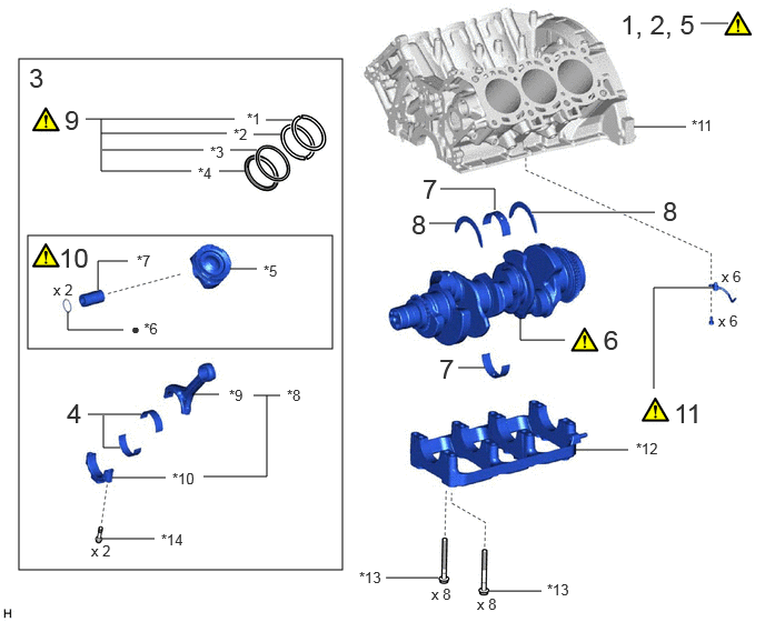
| Procedure | Part Name Code |

|

|

|
|
|---|---|---|---|---|---|
| 1 | INSPECT CONNECTING ROD THRUST CLEARANCE | - | ( ) |
- | - |
| 2 | INSPECT CONNECTING ROD OIL CLEARANCE | - | () |
- | - |
| 3 | PISTON SUB-ASSEMBLY WITH CONNECTING ROD | - | () |
- | - |
| 4 | CONNECTING ROD BEARING | 13041 | - | - | - |
| 5 | INSPECT CRANKSHAFT THRUST CLEARANCE | - | - | - | |
| 6 | CRANKSHAFT | 13411 | () |
- | - |
| 7 | CRANKSHAFT BEARING | - | - | - | - |
| 8 | UPPER CRANKSHAFT THRUST WASHER | 11791 | - | - | - |
| 9 | PISTON RING SET | 13011 | () |
- | - |
| 10 | PISTON SUB-ASSEMBLY WITH PIN | - | () |
- | - |
| 11 | NO. 1 OIL NOZZLE SUB-ASSEMBLY AND NO. 2 OIL NOZZLE SUB-ASSEMBLY | - | () |
- | - |
| *1 | NO. 1 COMPRESSION RING | *2 | NO. 2 COMPRESSION RING |
| *3 | OIL RING RAIL | *4 | OIL RING EXPANDER |
| *5 | PISTON | *6 | PISTON PIN HOLE SNAP RING |
| *7 | PISTON PIN | *8 | CONNECTING ROD SUB-ASSEMBLY |
| *9 | CONNECTING ROD | *10 | CONNECTING ROD CAP |
| *11 | CYLINDER BLOCK SUB-ASSEMBLY | *12 | CRANKSHAFT BEARING CAP SUB-ASSEMBLY |
| *13 | CRANKSHAFT BEARING CAP BOLT | *14 | CONNECTING ROD BOLT |
| ● | Non-reusable part | - | - |
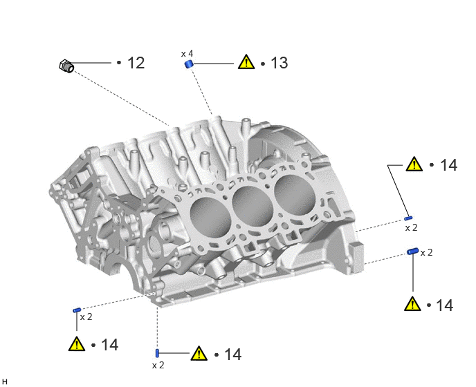
| Procedure | Part Name Code |
|
|
|
|
|---|---|---|---|---|---|
| 12 | CYLINDER BLOCK WATER DRAIN COCK PLUG | 11415A | - | - | - |
| 13 | RING PIN | - | () |
- | - |
| 14 | STRAIGHT PIN | - | () |
- | - |
| ● | Non-reusable part | - | - |
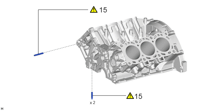
| Procedure | Part Name Code |
|
|
|
|
|---|---|---|---|---|---|
| 15 | STUD BOLT | - | () |
- | - |
CAUTION / NOTICE / HINT
The necessary procedures (adjustment, calibration, initialization, or registration) that must be performed after parts are removed, installed, or replaced during the cylinder block removal/installation are shown below.
| Replaced Part or Performed Procedure | Necessary Procedure | Effect/Inoperative Function when Necessary Procedure not Performed | Link |
|---|---|---|---|
| Battery terminal is disconnected/reconnected | Memorize steering angle neutral point | Parking assist monitor system | () |
| Multi-terrain monitor system | () |
||
| Panoramic view monitor system | () |
||
| Engine assembly | Perform road test to allow TCM to learn |
·
Large shift shock
·
Engine overruns |
() |
| Turbocharger sub-assembly | VN Turbo Offset Voltage Value Compensation |
·
Poor idle, etc.
·
Engine start function, etc. |
w/ DPF: ( ) w/o DPF: ( ) |
| Initialization | w/ DPF: ( ) w/o DPF: ( ) |
||
|
·
Diesel throttle body assembly
·
Electric EGR control valve assembly |
Initialization | - | |
| Automatic transmission fluid | ATF thermal degradation estimate reset | The value of the Data List item "ATF Thermal Degradation Estimate" is not estimated correctly. | () |
| Front bumper assembly (Including removal and installation) | Front television camera view adjustment | Panoramic view monitor system | () |
- HINT:
-
When the cable is disconnected/reconnected to the battery terminal, systems temporarily stop operating. However, each system has a function that completes learning the first time the system is used.
-
·
Learning completes when vehicle is driven
Effect/Inoperative Function When Necessary Procedures are not Performed Necessary Procedures Link Stop and start system Drive the vehicle until stop and start control is permitted (approximately 5 to 60 minutes). ( )Lighting system (EXT) Cornering lights Drive the vehicle straight ahead at 35 km/h (22 mph) or more for 5 seconds or more. ( )Pre-collision system Lane tracing assist system Lane departure alert system Adaptive high beam system
·Learning completes when vehicle is operated normally
Effect/Inoperative Function When Necessary Procedures are not Performed Necessary Procedures Link Power back door system Fully close the back door by hand.
- HINT:
-
Initialization is not necessary if the above procedures are performed while the back door is closed.
( )Air conditioning system After the ignition switch is turned to ON, the servo motor and expansion valve standard position is recognized. -
PROCEDURE

 1.INSPECT CONNECTING ROD THRUST CLEARANCE
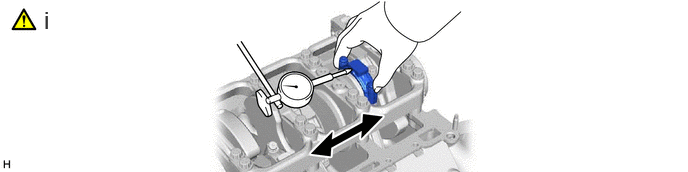
Using a dial indicator, measure the thrust clearance while moving the connecting rod back and forth.
- Standard thrust clearance:
-
0.15 to 0.54 mm (0.00591 to 0.0213 in.)
- Maximum thrust clearance:
-
0.60 mm (0.0236 in.)
- HINT:
-
If the thrust clearance is more than the maximum, replace the connecting rod sub-assembly. If necessary, replace the crankshaft.
2.INSPECT CONNECTING ROD OIL CLEARANCE
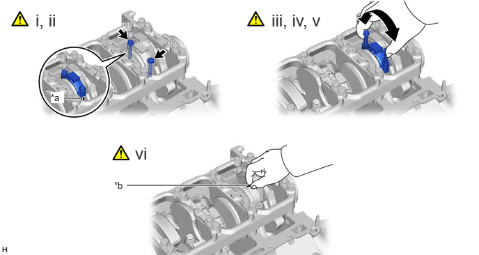
| *a | Matchmarks | *b | Plastigage |
Check that the matchmarks on the connecting rod and connecting rod cap are aligned.
- NOTICE:
-
The matchmarks on the connecting rod and connecting rod cap are guides for correct reassembly.
Remove the 2 connecting rod cap bolts.
Using the 2 removed connecting rod cap bolts, remove the connecting rod cap and lower bearing by wiggling the connecting rod cap right and left.
- HINT:
-
Keep the lower bearing inserted to the connecting rod cap.
Clean the crank pin and bearing.
Check the crank pin and bearing for pitting and scratches.
Lay a strip of Plastigage on the crank pin.
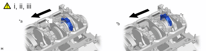
| *a | for Bank 1 (Piston RH) | *b | for Bank 2 (Piston LH) |
| *c | Piston Matchmark (Protrusion) | - | - |

|
Engine Front | - | - |
Check that the piston matchmark (protrusion) of the connecting rod cap is facing forward.
- NOTICE:
-
·
Take care as the piston matchmark (protrusion) on the piston RH connecting rod is reversed for the piston LH.
·The matchmarks on the connecting rod and connecting rod cap are guides for correct reassembly.
Install the connecting rod cap.
Click hereEngine / Hybrid System>F33A-FTV (ENGINE MECHANICAL)>CYLINDER BLOCK>REASSEMBLY
- NOTICE:
-
Do not turn the crankshaft.
Remove the 2 bolts and connecting rod cap.
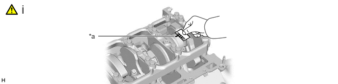
| *a | Plastigage | - | - |
Measure the Plastigage at its widest point.
- Standard oil clearance:
-
0.038 to 0.061 mm (0.00150 to 0.00240 in.)
- Maximum oil clearance:
-
0.071 mm (0.00280 in.)
If the oil clearance is more than the maximum, replace the connecting rod bearings. If necessary, inspect the crankshaft.
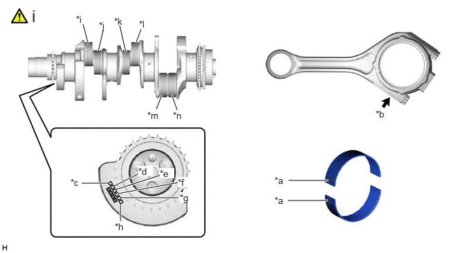
| *a | Connecting Rod Bearing Selection Code | *b | Connecting Rod Cap Selection Code |
| *c | Crankshaft Pin (1) Diameter Selection Code | *d | Crankshaft Pin (2) Diameter Selection Code |
| *e | Crankshaft Pin (3) Diameter Selection Code | *f | Crankshaft Pin (4) Diameter Selection Code |
| *g | Crankshaft Pin (5) Diameter Selection Code | *h | Crankshaft Pin (6) Diameter Selection Code |
| *i | Crankshaft Pin (1) | *j | Crankshaft Pin (2) |
| *k | Crankshaft Pin (3) | *l | Crankshaft Pin (4) |
| *m | Crankshaft Pin (5) | *n | Crankshaft Pin (6) |
If the clearance is the maximum or greater, select and replace the connecting rod bearing or replace the crankshaft.
- HINT:
-
If using a standard connecting rod bearing, replace it with one that has the same number. If the number of the connecting rod bearing cannot be determined, select the correct connecting rod bearing by adding together the numbers imprinted on the crankshaft and connecting rod cap, and then selecting the connecting rod bearing with the same number as the total. There are 5 sizes of standard connecting rod bearings, marked 2, 3, 4, 5 and 6.
-
EXAMPLE:
-
Connecting rod cap (A) "3" + Crankshaft (B) "1" = Total number 4 (Use connecting rod bearing (C) "4")
-
Connecting Rod Cap (A) Crankshaft (B) Use Connecting Rod Bearing (C) 1 0 1 1 2 2 3 2 0 2 1 3 2 4 3 0 3 1 4 2 5
| Item | Specified Condition |
|---|---|
| Mark 1 | 63.000 to 63.006 mm (2.4803 to 2.4805 in.) |
| Mark 2 | 63.007 to 63.012 mm (2.4806 to 2.4808 in.) |
| Mark 3 | 63.013 to 63.018 mm (2.4808 to 2.4810 in.) |
| Item | Specified Condition |
|---|---|
| Mark 0 | 59.995 to 60.000 mm (2.3620 to 2.3622 in.) |
| Mark 1 | 59.989 to 59.994 mm (2.3618 to 2.3620 in.) |
| Mark 2 | 59.982 to 59.988 mm (2.3615 to 2.3617 in.) |
| Item | Specified Condition |
|---|---|
| Mark 1 | 1.483 to 1.486 mm (0.0584 to 0.0585 in.) |
| Mark 2 | 1.487 to 1.489 mm (0.0585 to 0.0586 in.) |
| Mark 3 | 1.490 to 1.492 mm (0.0587 to 0.0587 in.) |
| Mark 4 | 1.493 to 1.495 mm (0.0588 to 0.0589 in.) |
| Mark 5 | 1.496 to 1.498 mm (0.0589 to 0.0590 in.) |
3.REMOVE PISTON SUB-ASSEMBLY WITH CONNECTING ROD
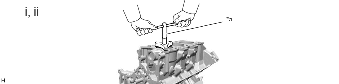
| *a | Ridge Reamer | - | - |
Using a ridge reamer, remove all the carbon from the top of the cylinder.
Push the piston, connecting rod sub-assembly and upper bearing through the top of the cylinder block sub-assembly.
- HINT:
-
·
Keep the bearing, connecting rod and cap together.
·Arrange the piston and connecting rod assemblies in the correct order.
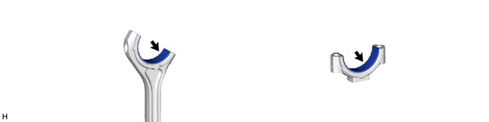
13041 4.REMOVE CONNECTING ROD BEARING
5.INSPECT CRANKSHAFT THRUST CLEARANCE
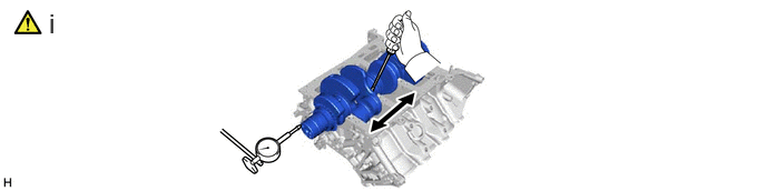
Using a dial indicator, measure the crankshaft thrust clearance while prying the crankshaft back and forth with a screwdriver.
- Standard thrust clearance:
-
0.04 to 0.19 mm (0.00157 to 0.00748 in.)
- Maximum thrust clearance:
-
0.25 mm (0.00984 in.)
If the thrust clearance is more than the maximum, replace the upper crankshaft thrust washers. If necessary, replace the crankshaft.
- Standard crankshaft thrust washer thickness:
-
2.44 to 2.49 mm (0.0961 to 0.0980 in.)
13411 6.REMOVE CRANKSHAFT
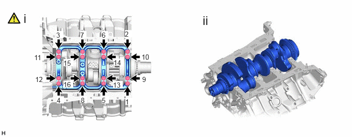
Uniformly loosen the 16 crankshaft bearing cap set bolts in several steps and in the sequence shown in the illustration.
Remove the crankshaft from the cylinder block sub-assembly.
7.REMOVE CRANKSHAFT BEARING
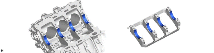
11791 8.REMOVE UPPER CRANKSHAFT THRUST WASHER
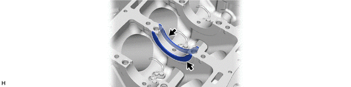
13011 9.REMOVE PISTON RING SET
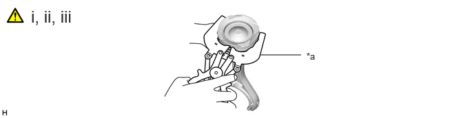
| *a | Piston Ring Expander | - | - |
Using a piston ring expander, remove the 2 compression rings.
Using a piston ring expander, remove the oil ring rail.
Remove the oil ring expander by hand.
- HINT:
-
Arrange the removed parts in the correct order.
10.REMOVE PISTON SUB-ASSEMBLY WITH PIN
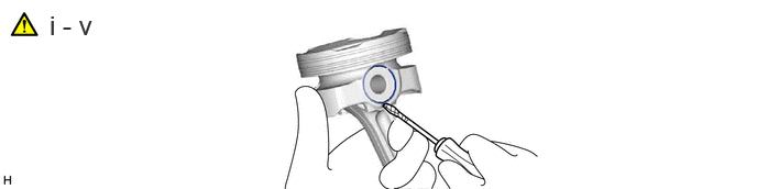
Using a screwdriver, pry off the piston pin hole snap rings from the piston.
- HINT:
-
Tape the screwdriver tip before use.
Remove the piston pin from the piston.
- HINT:
-
The piston and piston pin are a matched set.
Using a gasket scraper, remove the carbon from the piston top.
Using a groove cleaning tool or broken ring, clean the piston ring grooves.
Using solvent and a brush, thoroughly clean the piston.
- NOTICE:
-
Do not use a wire brush.
11.REMOVE NO. 1 OIL NOZZLE SUB-ASSEMBLY AND NO. 2 OIL NOZZLE SUB-ASSEMBLY
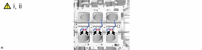
Using a 5 mm hexagon wrench, remove the 6 bolts, No. 1 oil nozzle sub-assemblies and No. 2 oil nozzle sub-assemblies.
Check the 6 No. 1 oil nozzle sub-assemblies and No. 2 oil nozzle sub-assemblies for damage or clogging.
If necessary, replace the No. 1 oil nozzle sub-assembly and No. 2 oil nozzle sub-assemblies .
11415A 12.REMOVE CYLINDER BLOCK WATER DRAIN COCK PLUG
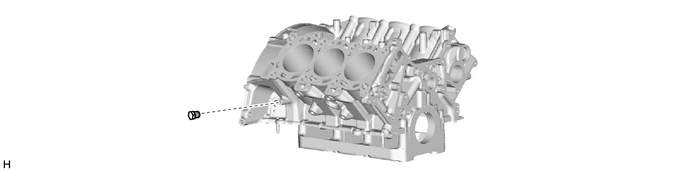
13.REMOVE RING PIN
|
|
|
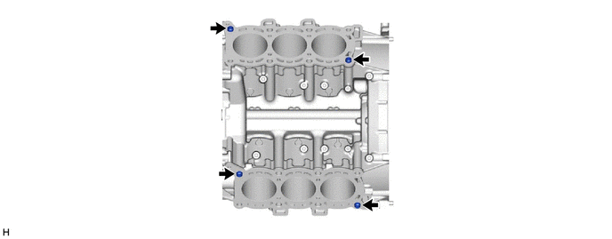
14.REMOVE STRAIGHT PIN
|
|
|
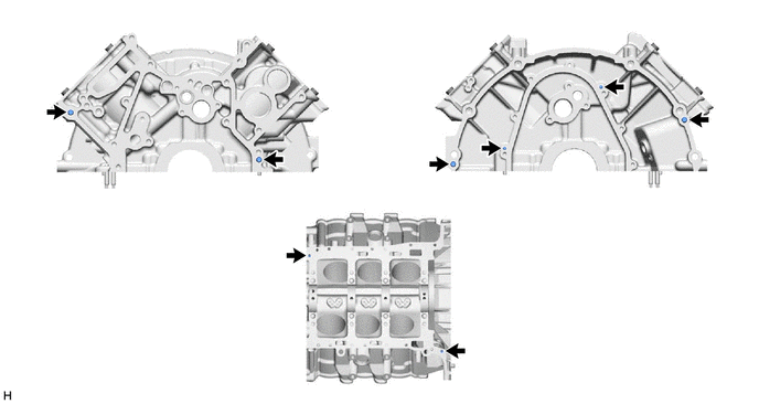
15.REMOVE STUD BOLT
|
|
|
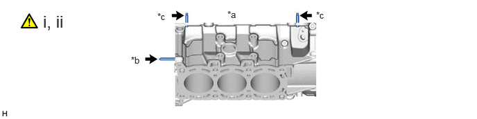
| *a | for Bank 1 | *b | Stud Bolt A |
| *c | Stud Bolt B | - | - |
Using an E7 "TORX" socket wrench, remove the stud bolts A.
Using an E8 "TORX" socket wrench, remove the stud bolts B.