F33A-FTV ENGINE MECHANICAL REAR CRANKSHAFT OIL SEAL REMOVAL
CAUTION / NOTICE / HINT
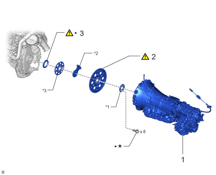
| Procedure | Part Name Code |

|

|

|
|
|---|---|---|---|---|---|
| 1 | AUTOMATIC TRANSMISSION ASSEMBLY WITH TRANSFER ASSEMBLY | - | - | - | - |
| 2 | DRIVE PLATE AND RING GEAR SUB-ASSEMBLY | 32101 | ( ) |
- | - |
| 3 | REAR ENGINE OIL SEAL | 11381A | () |
- | - |
| *1 | REAR DRIVE PLATE SPACER | *2 | REAR CRANKSHAFT BALANCER WEIGHT |
| *3 | NO. 1 CRANKSHAFT POSITION SENSOR PLATE | - | - |
| ● | Non-reusable part | ★ | Precoated part |
PROCEDURE

 1.REMOVE AUTOMATIC TRANSMISSION ASSEMBLY WITH TRANSFER ASSEMBLY
32101 2.REMOVE DRIVE PLATE AND RING GEAR SUB-ASSEMBLY
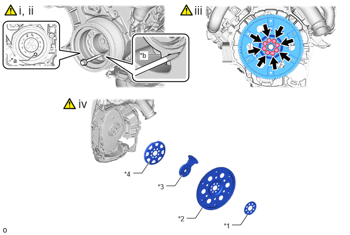
| *1 | Rear Drive Plate Spacer | *2 | Drive Plate And Ring Gear Sub-assembly |
| *3 | Rear Crankshaft Balancer Weight | *4 | No. 1 Crankshaft Position Sensor Plate |
| *a | Service Hole | *b | Protrusion |
Align the service hole of the crankshaft pulley sub-assembly with the position as shown in the illustration.
Install a service bolt and fix the crankshaft pulley sub-assembly.
| Length | 120 mm (4.72 in.) or more |
| Diameter | 14 mm (0.551 in.) |
| Pitch | 1.5 |
| Thread Length | 70 mm (2.76 in.) or more |
- HINT:
-
The crankshaft pulley sub-assembly is fixed by hooking a service bolt on the convex part of the timing chain cover sub-assembly.
Remove the 8 bolts.
Remove the rear drive plate spacer, drive plate and ring gear sub-assembly, rear crankshaft balancer Weight and No. 1 crankshaft position aensor plate.
11381A 3.REMOVE REAR ENGINE OIL SEAL
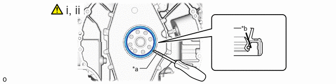
| *a | Protective Tape | *b | Cut Position |
Using a knife, cut through the lip of the rear engine oil seal.
Using a screwdriver with its tip taped, pry out the rear engine oil seal.
- NOTICE:
-
After removal, check the crankshaft for damage.