POWER ASSIST SYSTEMS POWER STEERING SYSTEM(w/ Variable Flow Control Solenoid Valve) Power Steering Warning Light Circuit
DESCRIPTION
Use the following procedure if no DTCs are output but the power steering warning light is illuminated continuously.
The power steering ECU with motor assembly and power steering ECU assembly controls the warning light in the combination meter assembly via CAN communication.
WIRING DIAGRAM
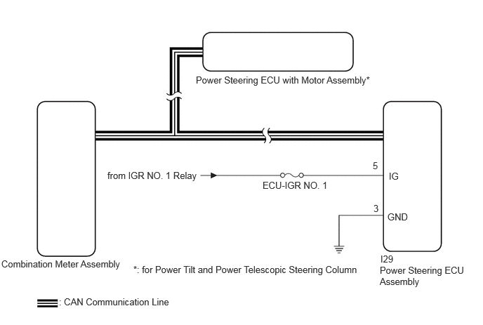
CAUTION / NOTICE / HINT
- NOTICE:
-
When the power steering ECU with motor assembly has been replaced, perform Steering Actuator ECU Initial Setting (assist map writing).
PROCEDURE
Check the vehicle specification.
- Result:
-
Result Proceed to for Manual Tilt and Manual Telescopic Steering Column A for Power Tilt and Power Telescopic Steering Column B
A
B
Disconnect the I29 power steering ECU assembly connector.
Measure the voltage according to the value(s) in the table below.
- Standard Voltage:
-
Tester Connection Switch Condition Specified Condition Click Location & Routing(I29)Location & Routingewd_type=routing;type=c;code=I29
I29-5 (IG) - Body ground Ignition switch ON 11 to 14 V
Measure the resistance according to the value(s) in the table below.
- Standard Resistance:
-
Tester Connection Condition Specified Condition Click Location & Routing(I29)Location & Routingewd_type=routing;type=c;code=I29
I29-3 (GND) - Body ground Always Below 1 Ω
- Result:
-
Proceed to OK NG
OK
NG
Click hereVehicle Interior>METER / GAUGE / DISPLAY>METER / GAUGE SYSTEM>HOW TO PROCEED WITH TROUBLESHOOTING
- Result:
-
Proceed to OK NG
OK
Click hereGeneral>INTRODUCTION>HOW TO TROUBLESHOOT ECU CONTROLLED SYSTEMS>HOW TO PROCEED WITH TROUBLESHOOTING
NG
Click hereVehicle Interior>METER / GAUGE / DISPLAY>METER / GAUGE SYSTEM>HOW TO PROCEED WITH TROUBLESHOOTING
Disconnect the I29 power steering ECU assembly connector.
Measure the voltage according to the value(s) in the table below.
- Standard Voltage:
-
Tester Connection Switch Condition Specified Condition Click Location & Routing(I29)Location & Routingewd_type=routing;type=c;code=I29
I29-5 (IG) - Body ground Ignition switch ON 11 to 14 V
Measure the resistance according to the value(s) in the table below.
- Standard Resistance:
-
Tester Connection Condition Specified Condition Click Location & Routing(I29)Location & Routingewd_type=routing;type=c;code=I29
I29-3 (GND) - Body ground Always Below 1 Ω
- Result:
-
Proceed to OK NG
OK
NG
Check the vehicle control history (RoB).
- Chassis > Steering Actuator > Utility
-
Tester Display Vehicle Control History (RoB) - 50005 499 55
- HINT:
-
The power steering warning light illuminates if any vehicle control history (RoB) is stored.
- Result:
-
Result Proceed to Vehicle control history (RoB) not stored for power steering ECU with motor assembly A Vehicle control history (RoB) stored for power steering ECU with motor assembly B
A
B
- NOTICE:
-
After performing troubleshooting and repair regarding vehicle control history (RoB), clear the vehicle control history (RoB).
Click hereVehicle Interior>METER / GAUGE / DISPLAY>METER / GAUGE SYSTEM>HOW TO PROCEED WITH TROUBLESHOOTING
- Result:
-
Proceed to OK NG
OK
NG
Click hereVehicle Interior>METER / GAUGE / DISPLAY>METER / GAUGE SYSTEM>HOW TO PROCEED WITH TROUBLESHOOTING
Read the Data List according to the display on the GTS.
- Chassis > Steering Actuator > Data List
-
Tester Display Measurement Item Range Normal Condition Diagnostic Note Battery Voltage Drop History Number of times vehicle battery voltage dropped Min.: 0
Max.: 255- - Engine Revolution Ready Signal Communication Failure History Vehicle speed input value sent via CAN (equal to value indicated on speedometer) Min.: 0
Max.: 255- - Steering Angle Sensor Signal Communication Failure History Number of times steering angle sensor signal was interrupted Min.: 0
Max.: 255- - Vehicle Speed Signal Invalid History Number of times steering angle sensor signal was interrupted Min.: 0
Max.: 255- - Overheat Prevention Control History Number of times assist limit performed due to estimated temperature of power steering ECU and motor coil Min.: 0
Max.: 255- - Power Supply Voltage Drop Control History Number of times assist limit performed due to battery voltage having dropped to 9 V or less Min.: 0
Max.: 255- - Power Supply Voltage Drop Restraint Control History Number of times assist limit performed due to battery voltage having dropped to 9.7 V or less Min.: 0
Max.: 255- - Engine Stall/READY OFF Control History Number of times assist limit performed due to engine stall Min.: 0
Max.: 255- - High Load Continuous Control Number of Times Number of times assist limit performed to prevent motor from overheating when overloaded due to steering wheel being turned to full lock position for an extended period of time, tire pressing against curbstone, etc. Min.: 0
Max.: 255- - Vehicle Speed Signal Fault Control History Number of times assist power set to a value suitable for high-speed driving when driving at high speeds due to an abnormal vehicle speed signal Min.: 0
Max.: 255- - Load Control History Number of times electric load limited to ensure stable vehicle power when power steering could not function appropriately or battery voltage was too low to ensure stable power steering Min.: 0
Min.: 0- -
- Chassis > Steering Actuator > Data List
-
Tester Display Battery Voltage Drop History Engine Revolution Ready Signal Communication Failure History Steering Angle Sensor Signal Communication Failure History Vehicle Speed Signal Invalid History Overheat Prevention Control History Power Supply Voltage Drop Control History Power Supply Voltage Drop Restraint Control History Engine Stall/READY OFF Control History High Load Continuous Control Number of Times Vehicle Speed Signal Fault Control History Load Control History - 50003 499 351,353,354,355,356,357,358,359,360,361,363
- HINT:
-
If the battery is not sufficiently charged or the voltage decreases temporarily, the amount of power assist will be reduced and the power steering warning light will come on. In such cases, the amount of power assist returns to normal when the battery voltage recovers.
- OK:
-
No control history
- Result:
-
Proceed to OK NG
OK
Click hereGeneral>INTRODUCTION>HOW TO TROUBLESHOOT ECU CONTROLLED SYSTEMS>HOW TO PROCEED WITH TROUBLESHOOTING
NG
Check for vehicle control history (RoB) and note any codes that are output.
- Chassis > Steering Actuator > Utility
-
Tester Display Vehicle Control History (RoB) - 50005 499 55
Record the vehicle control history (RoB).
- Result:
-
Result Proceed to Vehicle control history (RoB) is not output A Vehicle control history (RoB) other than (X206D) are output B Vehicle control history (RoB) (X206D) is output C
A
Click hereGeneral>INTRODUCTION>HOW TO TROUBLESHOOT ECU CONTROLLED SYSTEMS>HOW TO PROCEED WITH TROUBLESHOOTING
B
C
Check for vehicle control history (RoB) freeze frame data and note any codes that are output.
- Chassis > Steering Actuator > Utility
-
Tester Display Vehicle Control History (RoB) - 50005 499 55
Record the vehicle control history (RoB).
- Result:
-
Result Proceed to Vehicle control history (RoB) is not output A Vehicle control history (RoB) freeze frame data (Status of Vehicle Power (IGP PDC) is OFF) and (Status of Vehicle Power (IGR PDC) is OFF) are output B Vehicle control history (RoB) freeze frame data (Status of Vehicle Power (IGP PDC) is OFF) and (Status of Vehicle Power (IGR PDC) is ON) are output C
A
Click herePower Source / Network>NETWORKING>CAN COMMUNICATION SYSTEM>HOW TO PROCEED WITH TROUBLESHOOTING
B
for V35A-FTS: Click hereEngine / Hybrid System>V35A-FTS (ENGINE CONTROL)>SFI SYSTEM>PROBLEM SYMPTOMS TABLE
for F33A-FTV(w/ DPF): Click hereEngine / Hybrid System>F33A-FTV (ENGINE CONTROL)>ECD SYSTEM (w/ DPF)>PROBLEM SYMPTOMS TABLE
for F33A-FTV(w/o DPF): Click hereEngine / Hybrid System>F33A-FTV (ENGINE CONTROL)>ECD SYSTEM (w/o DPF)>PROBLEM SYMPTOMS TABLE
C
Check for vehicle control history freeze frame data and note any codes that are output.
- Body Electrical > SRS Airbag > Utility
-
Tester Display Vehicle Control History - 50005 444 54
| Tester Display | Measurement Item | Range | Diagnostic Note |
|---|---|---|---|
| Vehicle Speed | Vehicle speed at main driven wheels | 0 to 200 km/h | If the vehicle speed is 200 km/h or more, "200 km/h" is displayed. |
| Engine RPM Data | Number of crankshaft revolutions in 1 minute | 0 to 12800 rpm | - |
| Shift Position Signal | Shift lever position | N/D/R/P/5/4/3/2/LO/B/SD/S-Mode/Undetermined | - |
Record the vehicle control history.
- HINT:
-
If the engine is stopped while the vehicle is stationary and the shift lever is not in P, the power steering warning light (yellow) illuminates and the message "Engine Stopped Steering Power Low" will be displayed on the multi-information display in the combination meter assembly, but this is caused by incorrect operation and is not a malfunction.
- Result:
-
Result Proceed to Vehicle control history (vehicle speed 0 km/h or more, engine speed 0 rpm and shift position not in P) is output A Vehicle control history (vehicle speed 0 km/h or more, engine speed 0 rpm and shift position not in P) is not output B
A
If incorrect operation of the ignition switch causes unintended ignition switch off operation while the shift lever is not in P, the engine will stop thus causing power steering system shutdown and illumination of the power steering system warning light (yellow), but this is not a malfunction. (power steering system control during engine stall)
B
Click hereGeneral>INTRODUCTION>HOW TO TROUBLESHOOT ECU CONTROLLED SYSTEMS>HOW TO PROCEED WITH TROUBLESHOOTING