Home › Engine / Hybrid System › F33A-FTV (EMISSION CONTROL) › EXHAUST FUEL ADDITION INJECTOR › from 2021.07
RM38G0E _51 Engine / Hybrid System _106332 F33A-FTV EMISSION CONTROL _0491918 EXHAUST FUEL ADDITION INJECTOR A

F33A-FTV EMISSION CONTROL  EXHAUST FUEL ADDITION INJECTOR  INSTALLATION  


CAUTION / NOTICE / HINT
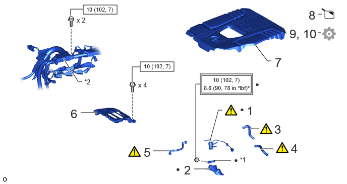
COMPONENTS (INSTALLATION)
A500088N03
2.896,1.281 3.594,1.479 0.698,0.198 1.719,0.104 2.417,0.292 0.698,0.188 4.135,1.531 5.219,1.958 1.083,0.427 4.167,1.563 5.188,1.927 1.021,0.365 5.271,0.927 5.521,1.26 5.521,1.26 5.604,1.26 true 1.667,2.333 2,2.333 true 3.167,3.125 3.5,3.125 true 5.396,3.083 5.646,3.083 true 5.167,2.667 5.344,2.667 true 4,3.5 4.333,3.5 true 4.333,2.938 4.51,2.281 4.51,2.281 4.594,2.281 true 1.302,1.198 1.615,1.688 1.615,1.688 1.698,1.688 true 2.729,1.698 2.729,1.385 2.729,1.385 2.896,1.385 false 1.458,0.323 1.458,0.188 1.458,0.188 1.708,0.188 false 4.042,3.281 4.042,1.74 4.042,1.74 4.135,1.74 false 4.438,3.323 4.771,3.323 false 6.573,0.677 6.635,0.677 false 6.573,0.292 6.656,0.292 false 5.094,2.146 5.448,2.5 0.354,0.354 18 false 1 1.458,2.208 1.74,2.563 0.281,0.354 18 false 6 2.854,1.677 3.104,1.844 0.25,0.167 10 false x 4 1.583,0.333 1.833,0.5 0.25,0.167 10 false x 2 1.74,1.615 1.99,1.781 0.25,0.167 10 false *2 3.802,3.375 4.313,3.635 0.51,0.26 18 false 2 3.635,3.417 4.094,3.615 0.458,0.198 10 false ● 5.667,2.531 6.177,2.792 0.51,0.26 18 false 3 6.01,2.927 6.521,3.188 0.51,0.26 18 false 4 2.969,3.01 3.427,3.396 0.458,0.385 18 false 5 5.677,1.146 6.031,1.5 0.354,0.354 18 false 7 6.375,0.167 6.719,0.51 0.344,0.344 18 false 8 5.979,0.552 6.677,0.896 0.698,0.344 18 false 9, 10 2.969,1.302 3.948,1.458 0.979,0.156 8 false 10 (102, 7) 1.781,0.125 2.76,0.281 0.979,0.156 8 false 10 (102, 7) 4.833,3.229 5.292,3.427 0.458,0.198 10 false ● *1 4.396,1.583 5.375,1.74 0.979,0.156 8 false 10 (102, 7) 4.208,1.75 5.188,1.906 0.979,0.156 8 false 8.8 (90, 78 in.*lbf)* 4.958,2.177 5.417,2.375 0.458,0.198 10 false ● 5.271,1.656 5.427,1.854 0.156,0.198 10 false ●

Procedure Part Name Code
Z101186

Z101188

Z101187

1 EXHAUST FUEL ADDITION INJECTOR ASSEMBLY 23710B (Click here) - -
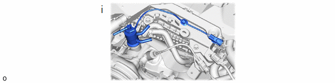
2 EXHAUST FUEL ADDITION INJECTOR HEAT INSULATOR 23600G - - -
3 NO. 21 WATER BY-PASS HOSE 1629H (Click here) - -
4 NO. 20 WATER BY-PASS HOSE 1629GA (Click here) -
5 FUEL TUBE SUB-ASSEMBLY 23901H (Click here) - -
6 INTERCOOLER INSULATOR 17951 - - -
7 NO. 1 ENGINE COVER SUB-ASSEMBLY 12601B - - -
8 ADD ENGINE COOLANT (for Intercooler) - - (Click here) -
9 INSPECT FOR COOLANT LEAK (for Intercooler) - - - (Click here)
10 BLEED FUEL LINE - - - (Click here)

*1 Exhaust pipe clamp sub-assembly *2 Engine wire
V111893

Tightening torque for "Major areas involving basic vehicle performance such as moving/turning/stopping": N*m (kgf*cm, ft.*lbf)
V100146

N*m (kgf*cm, ft.*lbf): Specified torque
* For use with union nut wrench ● Non-reusable part

PROCEDURE

Hide 23710B 1.INSTALL EXHAUST FUEL ADDITION INJECTOR ASSEMBLY

a.
A500089N01
2.135,0.063 2.375,0.385 0.24,0.323 18 false i

i.

Set a new exhaust fuel addition injector assembly to the exhaust manifold converter sub-assembly.


b.
A492978C01
0.396,0.094 0.677,0.448 0.281,0.354 18 false i 3.833,0.094 4.115,0.448 0.281,0.354 18 false ii 0.458,4.344 0.74,4.698 0.281,0.354 18 false iii 2.031,3.469 2.281,3.635 0.25,0.167 10 true *a 3.552,4.813 3.802,4.979 0.25,0.167 10 true *b 4.563,4.865 4.813,5.031 0.25,0.167 10 true *c 1.865,6.521 2.115,6.688 0.25,0.167 10 true *d
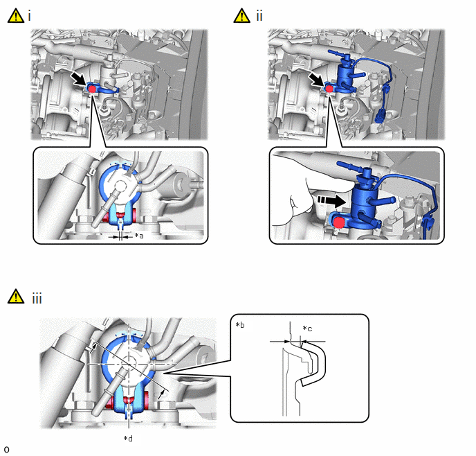
*a 6 mm (0.236 in.) *b Cutaway view
*c 2.5 mm (0.098 in.) or more *d Front side


i.

Install a new exhaust pipe clamp sub-assembly and tighten the nut until the end gap of the exhaust pipe clamp is 6 mm (0.236 in.).


ii.

Tighten the exhaust pipe clamp sub-assembly with a 10 mm union nut wrench while pushing the exhaust fuel addition injector assembly toward the rear of the vehicle.

Torque:
10 N*m (102 kgf*cm, 7 ft.*lbf)

HINT:
A329093

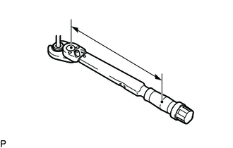
Calculate the torque wrench reading when changing the fulcrum length of the torque wrench.

When using SST (fulcrum length of 22 mm (0.86 in.)) + torque wrench (fulcrum length of 162 mm (6.37 in.)): 8.8 N*m (90 kgf*cm, 78 in.*lbf)


iii.

Measure the clearance between the exhaust fuel addition injector assembly and the exhaust pipe clamp sub-assembly.

Standard:

2.5 mm (0.098 in.) or more


NOTICE:

Do not reuse the exhaust fuel addition injector assembly and exhaust pipe clamp sub-assembly.


c.
A492979N01
2.115,0.073 2.396,0.427 0.281,0.354 18 false i

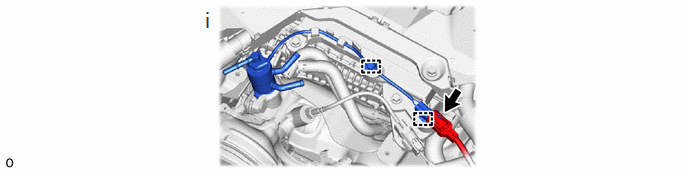
i.

Attach the 2 clamps and connect the connector.


Hide 23600G 2.INSTALL EXHAUST FUEL ADDITION INJECTOR HEAT INSULATOR

NOTICE:

If the contact clearance of the aluminum sheet is more than 5 mm (0.197 in.) , replace it.


Hide 1629H 3.CONNECT NO. 21 WATER BY-PASS HOSE
a.
A492983C01
5.917,1.25 5.833,1.25 5.833,1.25 5.625,0.844 true 4.167,0.5 4.25,0.5 4.25,0.5 4.521,0.615 true 4.771,1.146 5.083,1.344 0.313,0.198 10 false *a 5.375,0.396 5.688,0.594 0.313,0.198 10 false *b 5.781,0.396 6.094,0.594 0.313,0.198 10 false *b 5.979,1.167 6.292,1.365 0.313,0.198 10 false *c 3.948,0.427 4.26,0.625 0.313,0.198 10 false *c 0.375,0.031 0.656,0.385 0.281,0.354 18 false i
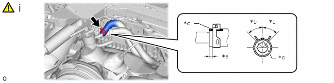
*a 2 to 6 mm (0.078 to 0.236 in.) *b 45°
*c Paint Mark - -


i.

Connect the No. 21 water by-pass hose and secure it with the hose clamp.


Hide 1629GA 4.CONNECT NO. 20 WATER BY-PASS HOSE
a.
A492984C01
5.917,1.25 5.833,1.25 5.833,1.25 5.625,0.844 true 4.167,0.5 4.25,0.5 4.25,0.5 4.521,0.615 true 4.771,1.146 5.083,1.344 0.313,0.198 10 false *a 5.375,0.396 5.688,0.594 0.313,0.198 10 false *b 5.781,0.396 6.094,0.594 0.313,0.198 10 false *b 5.979,1.167 6.292,1.365 0.313,0.198 10 false *c 3.948,0.427 4.26,0.625 0.313,0.198 10 false *c 0.375,0.031 0.656,0.385 0.281,0.354 18 false i
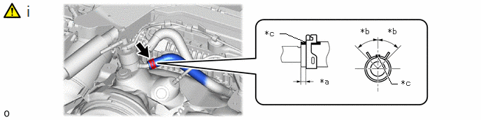
*a 2 to 6 mm (0.078 to 0.236 in.) *b 45°
*c Paint Mark - -


i.

Connect the No. 20 water by-pass hose and secure it with the hose clamp.


Hide 23901H 5.CONNECT FUEL TUBE SUB-ASSEMBLY
a.
A492971N01
1.938,0.083 2.208,0.49 0.271,0.406 18 false i

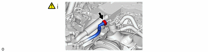
i.

Connect the fuel tube sub-assembly.

Click hereEngine / Hybrid System>F33A-FTV (FUEL)>FUEL SYSTEM>PRECAUTION


Hide 17951 6.INSTALL INTERCOOLER INSULATOR

Torque:
10 N*m (102 kgf*cm, 7 ft.*lbf)

Hide 12601B 7.INSTALL NO. 1 ENGINE COVER SUB-ASSEMBLY

Hide 8.ADD ENGINE COOLANT (for Intercooler)

Hide 9.INSPECT FOR COOLANT LEAK (for Intercooler)