RM38G0E _51 Engine / Hybrid System _106332 F33A-FTV EMISSION CONTROL _0491919 DIFFERENTIAL PRESSURE SENSOR A
F33A-FTV EMISSION CONTROL DIFFERENTIAL PRESSURE SENSOR INSTALLATION
CAUTION / NOTICE / HINT
COMPONENTS (INSTALLATION)
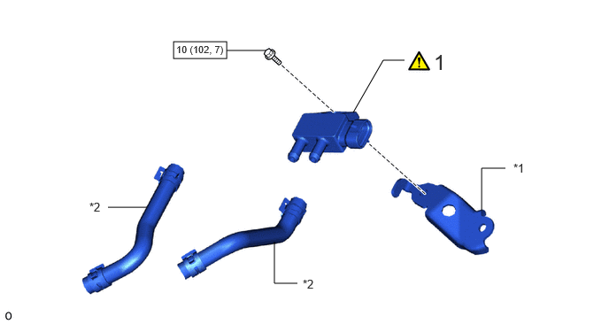
2.042,0.49 2.667,0.688 0.625,0.198 1.271,2.438 1.729,2.438 false 3.5,3.333 3.229,3.333 3.229,3.333 3.229,2.844 false 5.667,2.479 5.667,1.979 5.667,1.979 5.948,1.979 false 4.156,1.323 4.51,0.708 4.51,0.708 4.76,0.708 false 2.667,0.594 3.125,0.594 false 5.104,0.583 5.365,0.885 0.26,0.302 18 false 1 6.042,1.896 6.354,2.094 0.313,0.198 10 false *1 3.563,3.26 3.875,3.458 0.313,0.198 10 false *2 1.052,2.354 1.365,2.552 0.313,0.198 10 false *2 2.073,0.51 3.052,0.667 0.979,0.156 8 false 10 (102, 7)
| Procedure | Part Name Code |

|

|

|
|
|---|---|---|---|---|---|
| 1 | DIFFERENTIAL PRESSURE SENSOR | 89481B | ( ) |
- | - |
| *1 | Sensor bracket | *2 | Air hose |

|
N*m (kgf*cm, ft.*lbf): Specified torque | - | - |
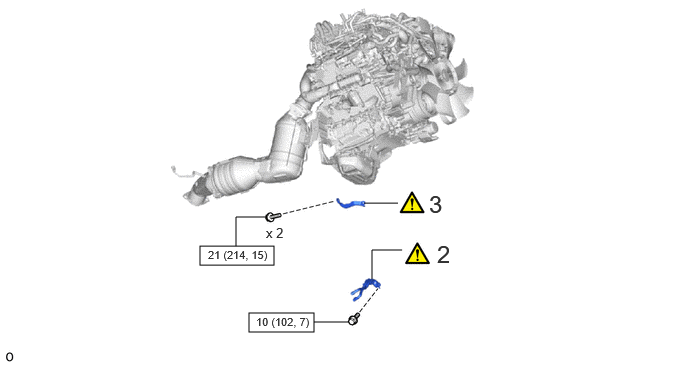
2.083,2.563 2.854,2.76 0.771,0.198 2.594,3.26 3.271,3.458 0.677,0.198 3.875,2.906 3.875,2.604 3.875,2.604 4.188,2.604 false 3.792,2.115 4.146,2.115 false 3.271,3.354 3.635,3.354 false 2.458,2.563 2.458,2.26 2.458,2.26 2.771,2.26 false 4.552,2.5 4.833,2.854 0.281,0.354 18 false 2 4.469,1.979 4.74,2.271 0.271,0.292 18 false 3 2.771,2.344 3.083,2.542 0.313,0.198 10 false x 2 2.667,3.281 3.646,3.438 0.979,0.156 8 false 10 (102, 7) 2.167,2.583 3.146,2.74 0.979,0.156 8 false 21 (214, 15)
| Procedure | Part Name Code |
|
|
|
|
|---|---|---|---|---|---|
| 2 | DIFFERENTIAL PRESSURE SENSOR ASSEMBLY | - | () |
- | - |
| 3 | INTAKE AIR CONNECTOR BRACKET | 17872 | () |
- | - |
|
|
N*m (kgf*cm, ft.*lbf): Specified torque | - | - |
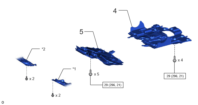
3.719,2.979 4.458,3.188 0.74,0.208 5.938,2.656 6.719,2.865 0.781,0.208 0.958,2.177 1.156,1.771 1.156,1.771 1.438,1.771 false 2.094,2.906 2.292,2.5 2.292,2.5 2.573,2.5 false 3.719,3.083 3.271,3.083 3.271,3.083 3.271,2.729 false 6.313,2.656 6.313,2.24 false 3.542,1.75 3.365,1.146 3.365,1.146 3.052,1.146 false 4.781,0.979 4.604,0.375 4.604,0.375 4.292,0.375 false 2.01,3.375 2.323,3.573 0.313,0.198 10 false x 2 1.063,2.771 1.375,2.969 0.313,0.198 10 false x 2 3.406,2.604 3.719,2.802 0.313,0.198 10 false x 5 6.438,2.094 6.75,2.292 0.313,0.198 10 false x 4 2.625,2.417 2.938,2.615 0.313,0.198 10 false *1 1.51,1.698 1.823,1.896 0.313,0.198 10 false *2 4.094,0.24 4.375,0.594 0.281,0.354 18 false 4 2.875,1 3.167,1.292 0.292,0.292 18 false 5 3.771,3.01 4.75,3.167 0.979,0.156 8 false 29 (296, 21) 6.031,2.688 7.01,2.844 0.979,0.156 8 false 29 (296, 21)
| Procedure | Part Name Code |
|
|
|
|
|---|---|---|---|---|---|
| 4 | NO. 2 ENGINE UNDER COVER ASSEMBLY | 51420 | - | - | - |
| 5 | NO. 1 ENGINE UNDER COVER ASSEMBLY | 51410 | - | - | - |
| *1 | ENGINE SIDE COVER SUB-ASSEMBLY LH | *2 | ENGINE SIDE COVER SUB-ASSEMBLY RH |
|
|
N*m (kgf*cm, ft.*lbf): Specified torque | - | - |
PROCEDURE

 89481B 1.INSTALL DIFFERENTIAL PRESSURE SENSOR
a.
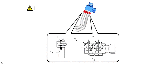
2.417,2.25 2.542,2.25 2.542,2.25 2.635,2.104 true 3.823,1.854 4.052,2.438 4.052,2.438 4.25,1.865 true 2.75,1.688 3.156,1.688 false 2.719,1.719 3.156,1.719 false 1.479,0.198 1.792,0.531 0.313,0.333 18 false i 2.167,2.167 2.417,2.333 0.25,0.167 10 false *a 3.979,2.479 4.229,2.646 0.25,0.167 10 false *a 3.948,1.51 4.198,1.677 0.25,0.167 10 false *b 3.208,1.615 3.521,1.813 0.313,0.198 10 false *c
| *a | Paint Mark | *b | Right side of the vehicle |
| *c | 0 to 2 mm (0 to 0.079 in.) | - | - |
i.
Connect the 2 air hoses to the differential pressure sensor and secure them with the 2 hose clamps.
b.
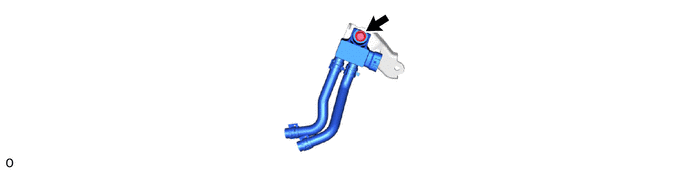
- Torque:
- 10 N*m (102 kgf*cm, 7 ft.*lbf)
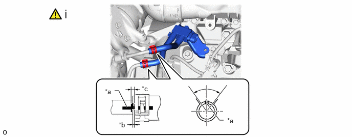
2.INSTALL DIFFERENTIAL PRESSURE SENSOR ASSEMBLY
a.
2.333,1.854 2.417,1.854 2.417,1.854 2.583,2.188 true 4.208,2.115 4.469,2.458 4.469,2.458 4.552,2.458 true 1.313,0.135 1.594,0.49 0.281,0.354 18 false i 2.135,1.792 2.448,1.99 0.313,0.198 10 false *a 2.417,2.469 2.729,2.667 0.313,0.198 10 false *b 4.625,2.385 4.938,2.583 0.313,0.198 10 false *a 2.885,1.729 3.198,1.927 0.313,0.198 10 false *c
| *a | Paint Mark | *b | 2 mm (0.079 in.) or more |
| *c | Position of the hose end | - | - |
i.
Connect the 2 air hoses and secure them with the 2 hose clamps.
b.
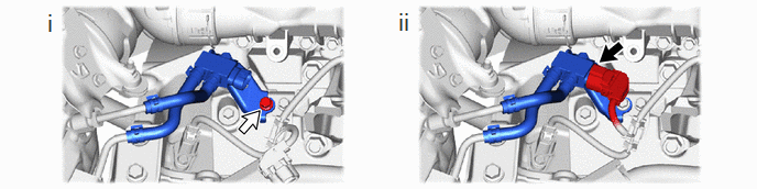
0.427,0.083 0.708,0.438 0.281,0.354 18 false i 3.75,0.073 4.031,0.427 0.281,0.354 18 false ii
i.
Install the differential pressure sensor assembly with the bolt.
- Torque:
- 10 N*m (102 kgf*cm, 7 ft.*lbf)
ii.
Connect the connector to the differential pressure sensor assembly.
17872 3.INSTALL INTAKE AIR CONNECTOR BRACKET
|
|
() |
51420 4.INSTALL NO. 2 ENGINE UNDER COVER ASSEMBLY
51410 5.INSTALL NO. 1 ENGINE UNDER COVER ASSEMBLY