F33A-FTV INTAKE / EXHAUST INTAKE MANIFOLD INSTALLATION
CAUTION / NOTICE / HINT
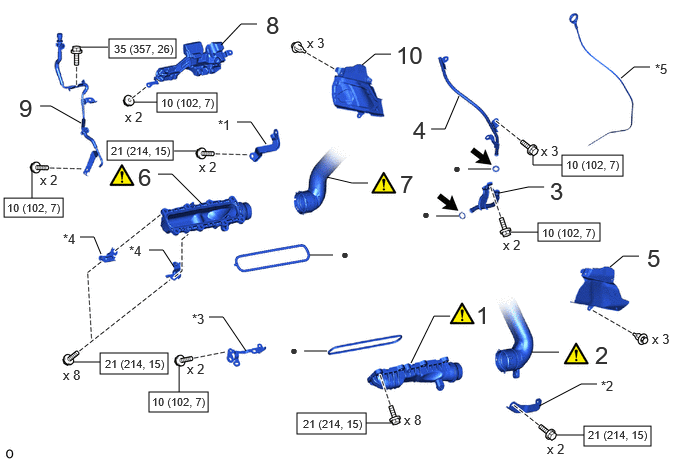
| Procedure | Part Name Code |

|

|

|
|
|---|---|---|---|---|---|
| 1 | NO. 2 INTAKE MANIFOLD | 17112 | ( ) |
- | - |
| 2 | NO. 2 INTAKE AIR CONNECTOR PIPE | 17877 | () |
- | - |
| 3 | ENGINE OIL LEVEL DIPSTICK GUIDE | 11452 | - | - | - |
| 4 | NO. 2 ENGINE OIL LEVEL DIPSTICK GUIDE | 12142 | - | - | - |
| 5 | FRONT FENDER APRON TRIM PACKING D | 53785B | - | - | - |
| 6 | INTAKE MANIFOLD | 17111 | () |
- | - |
| 7 | INTAKE AIR CONNECTOR PIPE | 17875 | () |
- | - |
| 8 | INTAKE MANIFOLD INSULATOR | 17853B | - | - | - |
| 9 | STARTER HOSE BRACKET SUB-ASSEMBLY | 28101 | - | - | - |
| 10 | FRONT FENDER APRON TRIM PACKING C | 53784 | - | - | - |
| *1 | INTAKE AIR CONNECTOR BRACKET | *2 | NO. 2 INTAKE AIR CONNECTOR BRACKET |
| *3 | NO. 2 WIRE HARNESS CLAMP | *4 | MANIFOLD STAY |
| *5 | ENGINE OIL LEVEL DIPSTICK | - | - |

|
N*m (kgf*cm, ft.*lbf): Specified torque |

|
Engine oil |
| ● | Non-reusable part | - | - |
PROCEDURE

 17112 1.INSTALL NO. 2 INTAKE MANIFOLD
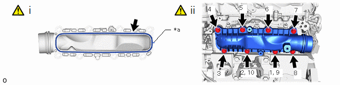
| *a | Protrusion | - | - |
Install a new gasket as shown in the illustration.
Install the No. 2 intake manifold with 8 bolts in the sequence shown in the illustration.
- Torque:
- 21 N*m (214 kgf*cm, 15 ft.*lbf)
17877 2.CONNECT NO. 2 INTAKE AIR CONNECTOR PIPE
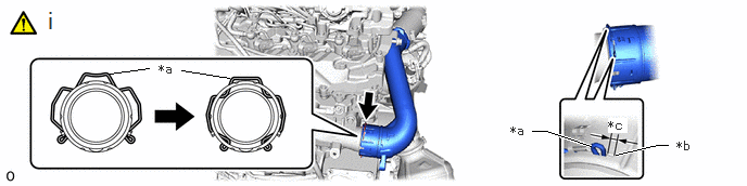
| *a | Retainer | *b | Stopper |
| *c | 0 to 3.0 mm (0 to 0.118 in.) | - | - |
Connect the No. 2 intake air connector pipe to the No. 2 intake manifold and lock the retainer.
- NOTICE:
-
Securely insert the retainer so that the locks are engaged. Then, pull and check that the locks are engaged and that the hose cannot be pulled out.
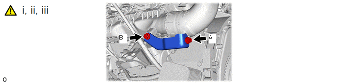
Temporarily install the No. 2 intake air connector bracket with bolts in the order A, B.
Tighten the bolt B.
- Torque:
- 21 N*m (214 kgf*cm, 15 ft.*lbf)
Tighten the bolt A.
- Torque:
- 21 N*m (214 kgf*cm, 15 ft.*lbf)
11452 3.INSTALL ENGINE OIL LEVEL DIPSTICK GUIDE
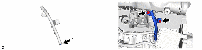
| *a | Apply a light coat of engine oil | - | - |
- Torque:
- 10 N*m (102 kgf*cm, 7 ft.*lbf)
12142 4.INSTALL NO. 2 ENGINE OIL LEVEL DIPSTICK GUIDE
53785B 5.INSTALL FRONT FENDER APRON TRIM PACKING D
17111 6.INSTALL INTAKE MANIFOLD
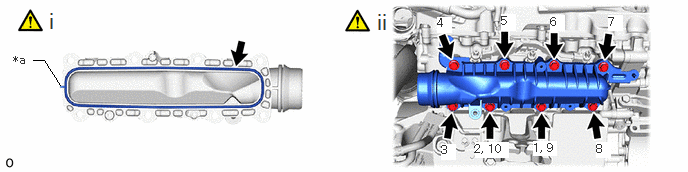
| *a | Protrusion | - | - |
Install a new gasket as shown in the illustration.
Install the intake manifold with 8 bolts in the sequence shown in the illustration.
- Torque:
- 21 N*m (214 kgf*cm, 15 ft.*lbf)

- Torque:
- 10 N*m (102 kgf*cm, 7 ft.*lbf)
17875 7.CONNECT INTAKE AIR CONNECTOR PIPE
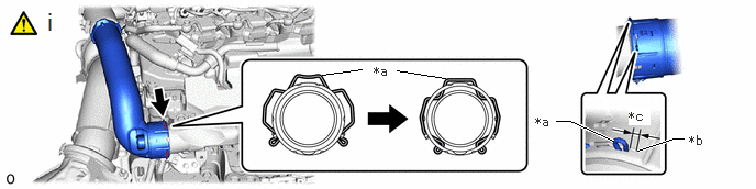
| *a | Retainer | *b | Stopper |
| *c | 0 to 3.0 mm (0 to 0.118 in.) | - | - |
Connect the intake air connector pipe to the intake manifold and lock the retainer.
- NOTICE:
-
Securely insert the retainer so that the locks are engaged. Then, pull and check that the locks are engaged and that the hose cannot be pulled out.
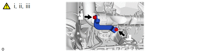
Temporarily install the intake air connector bracket with bolts in the order A, B.
Tighten the bolt B.
- Torque:
- 21 N*m (214 kgf*cm, 15 ft.*lbf)
Tighten the bolt A.
- Torque:
- 21 N*m (214 kgf*cm, 15 ft.*lbf)
17853B 8.INSTALL INTAKE MANIFOLD INSULATOR
28101 9.INSTALL STARTER HOSE BRACKET SUB-ASSEMBLY
53784 10.INSTALL FRONT FENDER APRON TRIM PACKING C