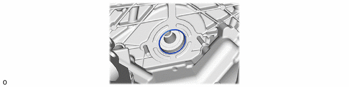
F33A-FTV FUEL FUEL SUPPLY PUMP REMOVAL
CAUTION / NOTICE / HINT
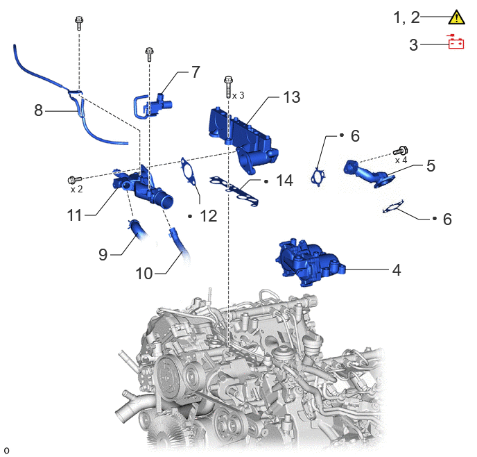
| Procedure | Part Name Code |

|

|

|
|
|---|---|---|---|---|---|
| 1 | PRECAUTION FOR WORK | - | ( ) |
- | - |
| 2 | PRECAUTION | - | () |
- | - |
| 3 | DISCONNECT CABLE FROM NEGATIVE BATTERY TERMINAL | - | - | - | - |
| 4 | DIESEL FUEL FILTER ASSEMBLY | 23300D | - | - | - |
| 5 | NO. 2 WATER OUTLET PIPE | 16335B | - | - | - |
| 6 | WATER OUTLET GASKET | 16341 | - | - | - |
| 7 | NO. 1 VACUUM SWITCHING VALVE ASSEMBLY | 25860 | - | - | - |
| 8 | NO. 1 VACUUM TRANSMITTING PIPE SUB-ASSEMBLY | 25706 | - | - | - |
| 9 | WATER HOSE | 16571E | - | - | - |
| 10 | NO. 4 OIL COOLER HOSE | 15776A | - | - | - |
| 11 | WATER OUTLET | 16331 | - | - | - |
| 12 | WATER OUTLET HOUSING GASKET | 16343 | - | - | - |
| 13 | TURBOCHARGER STAY | 17293 | - | - | - |
| 14 | TURBO OIL INLET GASKET | 15471 | - | - | - |
| ● | Non-reusable part | - | - |
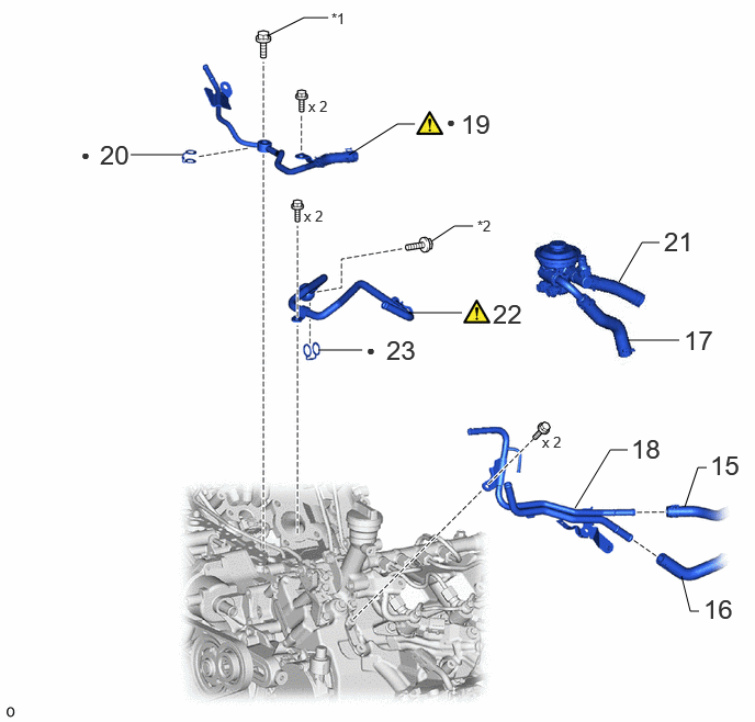
| Procedure | Part Name Code |
|
|
|
|
|---|---|---|---|---|---|
| 15 | NO. 2 FUEL HOSE | 23273H | - | - | - |
| 16 | NO. 1 FUEL HOSE | 23271H | - | - | - |
| 17 | NO. 3 FUEL HOSE | 23274D | - | - | - |
| 18 | NO. 2 FUEL PIPE | 23812D | - | - | - |
| 19 | NO. 5 NOZZLE LEAKAGE PIPE | 23765 | () |
- | - |
| 20 | GASKET | 23801N | - | - | - |
| 21 | NO. 4 FUEL HOSE | 23282D | - | - | - |
| 22 | NO. 1 FUEL PIPE | 23811G | () |
- | - |
| 23 | GASKET | 23811K | - | - | - |
| *1 | NOZZLE LEAKAGE PIPE SCREW | *2 | INJECTOR FOLLOW SCREW |
| ● | Non-reusable part | - | - |
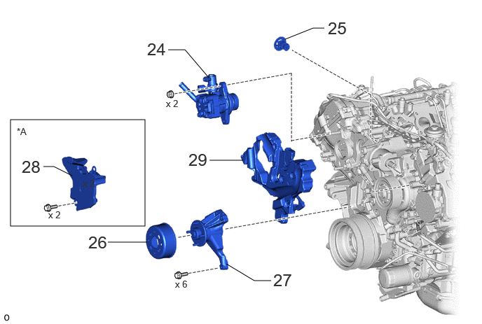
| Procedure | Part Name Code |
|
|
|
|
|---|---|---|---|---|---|
| 24 | VANE PUMP ASSEMBLY | 44310 | - | - | - |
| 25 | THERMOSTAT | 16331A | - | - | - |
| 26 | FAN PULLEY | 16371 | - | - | - |
| 27 | FAN BRACKET SUB-ASSEMBLY | 16307A | - | - | - |
| 28 | NO. 2 TIMING GEAR CASE INSULATOR | 11338A | - | - | - |
| 29 | TIMING CHAIN COVER INSULATOR | 11336B | - | - | - |
| *A | w/o Viscous Heater | - | - |
| Procedure | Part Name Code |
|
|
|
|
|---|---|---|---|---|---|
| 30 | TIMING CHAIN COVER PLATE | 11324 | - | - | - |
| 31 | NO. 2 TIMING CHAIN COVER GASKET | 11329B | - | - | - |
| 32 | INJECTION OR SUPPLY PUMP ASSEMBLY | 22100 | () |
- | - |
| 33 | INJECTION PUMP O-RING | 22100V | - | - | - |
| *1 | SUPPLY PUMP DRIVE COUPLING | - | - |
| ● | Non-reusable part | - | - |
CAUTION / NOTICE / HINT
The necessary procedures (adjustment, calibration, initialization, or registration) that must be performed after parts are removed, installed, or replaced during the injection or supply pump assembly removal/installation are shown below.
| Replaced Part or Performed Procedures | Necessary Procedures | Effect/Inoperative Function when Necessary Procedures are not Performed | Link |
|---|---|---|---|
| Battery terminal is disconnected/reconnected | Memorize steering angle neutral point | Parking assist monitor system | () |
| Multi-terrain monitor system | () |
||
| Panoramic view monitor system | () |
- HINT:
-
When the cable is disconnected/reconnected to the battery terminal, systems temporarily stop operating. However, each system has a function that completes learning the first time the system is used.
-
·
Learning completes when vehicle is driven
Effect/Inoperative Function When Necessary Procedures are not Performed Necessary Procedures Link Stop and start system Drive the vehicle until stop and start control is permitted (approximately 5 to 60 minutes) ( )Lighting system (EXT) Cornering lights Drive the vehicle straight ahead at 35 km/h (22 mph) or more for 5 seconds or more. ( )Pre-collision system Lane tracing assist system Lane departure alert system Adaptive high beam system
·Learning completes when vehicle is operated normally
Effect/Inoperative Function When Necessary Procedures are not Performed Necessary Procedures Link Power back door system Fully close the back door by hand.
- HINT:
-
Initialization is not necessary if the above procedures are performed while the back door is closed.
( )Air conditioning system After the ignition switch is turned to ON, the servo motor and expansion valve standard position is recognized. -
- CAUTION:
-
·
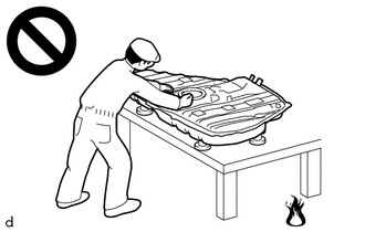
Never perform work on fuel system components near any possible ignition sources.
·Vaporized fuel could ignite, resulting in a serious accident.
-
·
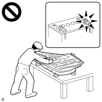
Do not perform work on fuel system components without first disconnecting the cable from the negative (-) battery terminal.
·Sparks could cause vaporized fuel to ignite, resulting in a serious accident.
PROCEDURE

 1. PRECAUTION FOR WORK
|
|
|
2. PRECAUTION
|
|
|
3.DISCONNECT CABLE FROM NEGATIVE BATTERY TERMINAL
23300D 4.REMOVE DIESEL FUEL FILTER ASSEMBLY
16335B 5.REMOVE NO. 2 WATER OUTLET PIPE
16341 6.REMOVE WATER OUTLET GASKET
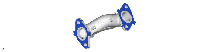
25860 7.REMOVE NO. 1 VACUUM SWITCHING VALVE ASSEMBLY
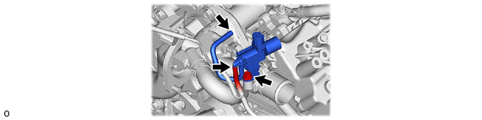
25706 8.REMOVE NO. 1 VACUUM TRANSMITTING PIPE SUB-ASSEMBLY
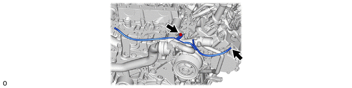
16571E 9.DISCONNECT WATER HOSE
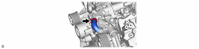
15776A 10.DISCONNECT NO. 4 OIL COOLER HOSE
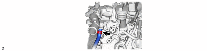
16331 11.REMOVE WATER OUTLET
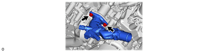
16343 12.REMOVE WATER OUTLET HOUSING GASKET
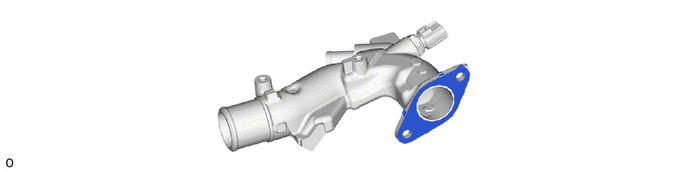
17293 13.REMOVE TURBOCHARGER STAY
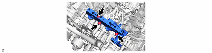
15471 14.REMOVE TURBO OIL INLET GASKET
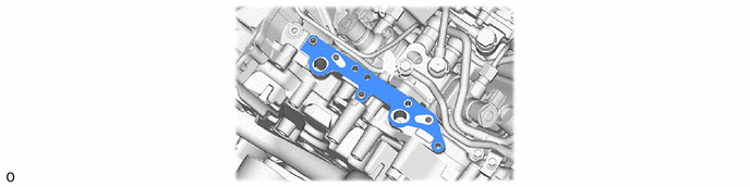
23273H 15.DISCONNECT NO. 2 FUEL HOSE
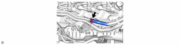
23271H 16.DISCONNECT NO. 1 FUEL HOSE
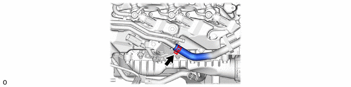
23274D 17.DISCONNECT NO. 3 FUEL HOSE
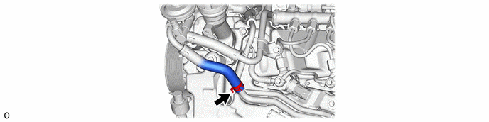
23812D 18.REMOVE NO. 2 FUEL PIPE
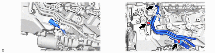
23765 19.REMOVE NO. 5 NOZZLE LEAKAGE PIPE
|
|
|
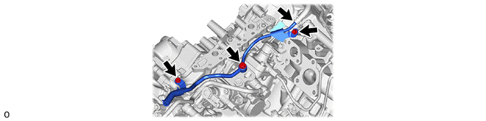
23801N 20.REMOVE GASKET
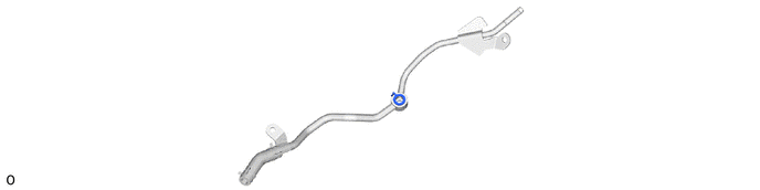
23282D 21.DISCONNECT NO. 4 FUEL HOSE
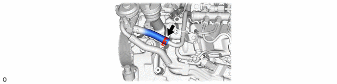
23811G 22.REMOVE NO. 1 FUEL PIPE
|
|
|
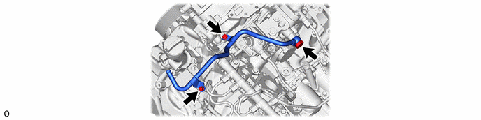
23811K 23.REMOVE GASKET
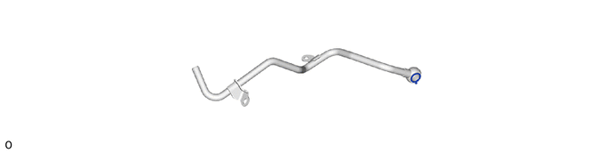
44310 24.DISCONNECT VANE PUMP ASSEMBLY
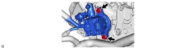
16331A 25.REMOVE THERMOSTAT
16371 26.REMOVE FAN PULLEY
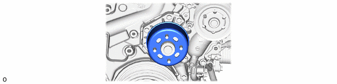
16307A 27.REMOVE FAN BRACKET SUB-ASSEMBLY
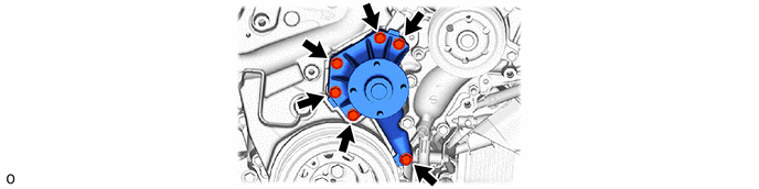
11338A 28.REMOVE NO. 2 TIMING GEAR CASE INSULATOR (w/o Viscous Heater)
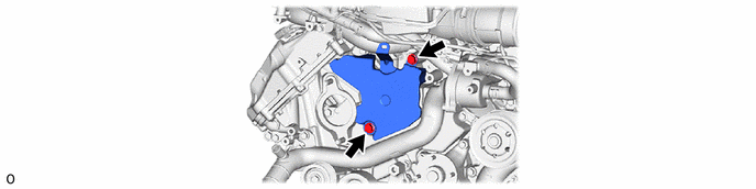
11336B 29.REMOVE TIMING CHAIN COVER INSULATOR
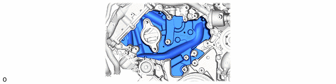
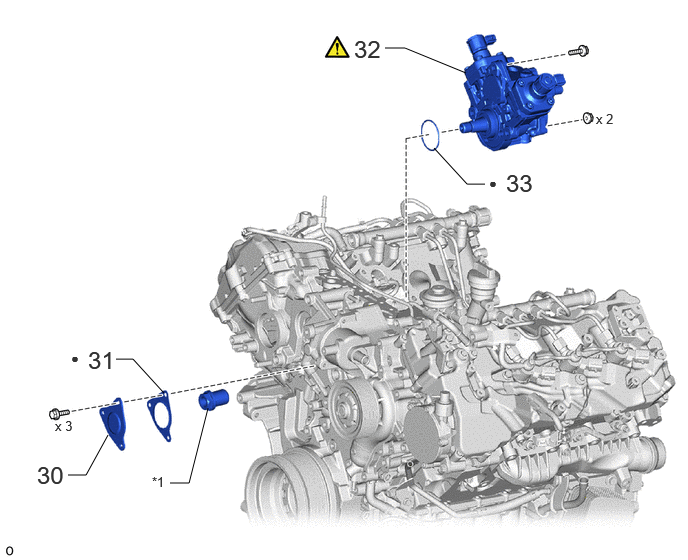
11324 30.REMOVE TIMING CHAIN COVER PLATE
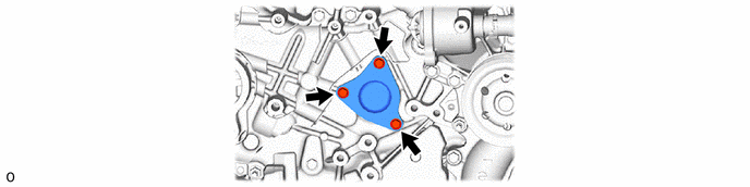
11329B 31.REMOVE NO. 2 TIMING CHAIN COVER GASKET
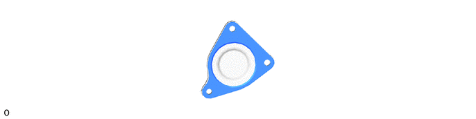
22100 32.REMOVE INJECTION OR SUPPLY PUMP ASSEMBLY
|
|
|
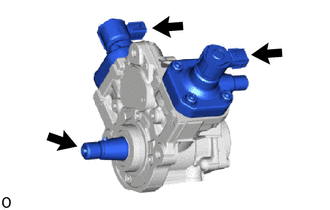
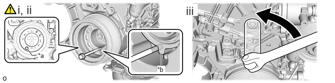
| *a | Service Hole | *b | Protrusion |
Align the service hole of the crankshaft pulley sub-assembly with the position as shown in the illustration.
Install a service bolt and fix the crankshaft pulley sub-assembly.
| Length | 120 mm (4.72 in.) or more |
| Diameter | 14 mm (0.551 in.) |
| Pitch | 1.5 |
| Thread Length | 70 mm (2.76 in.) or more |
- HINT:
-
The crankshaft pulley sub-assembly is fixed by hooking a service bolt on the convex part of the timing chain cover sub-assembly.
Using a 27 mm deep socket wrench, rotate the supply pump drive coupling once to loosen it.
- NOTICE:
-
Do not excessively loosen the supply pump shaft nut, otherwise SST cannot be installed.
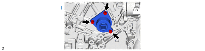
Align the hexagonal portion of SST with the supply pump drive coupling, install the SST to the timing chain or belt cover sub-assembly with the 3 bolts.
- SST
-
09241-11010
- Torque:
- 10 N*m (102 kgf*cm, 7 ft.*lbf)
- NOTICE:
-
·
Install SST with the bolts included with SST.
·SST holds the supply pump shaft sprocket, do not remove the SST until the injection or supply pump assembly is installed.
- HINT:
-
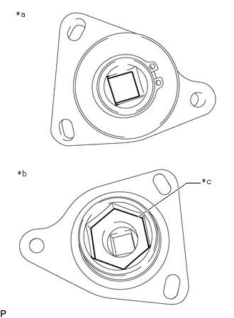 2.021,3.188 2.74,2.688 2.74,2.688 2.938,2.688 true 0.24,0.135 0.552,0.292 0.313,0.156 10 false *a 0.26,2.479 0.573,2.635 0.313,0.156 10 false *b 2.969,2.594 3.281,2.75 0.313,0.156 10 false *c
*a Engine Front Side *b Supply Pump Drive Coupling Side *c Hexagonal Portion
-
Make sure that the installation direction of SST is as shown in the illustration.
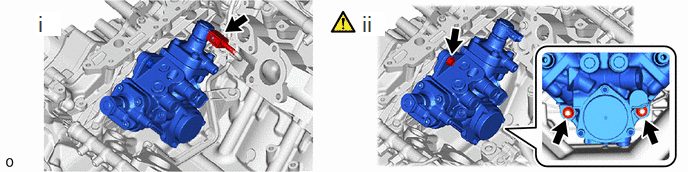
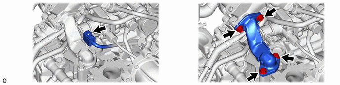
Disconnect the connector from the injection or supply pump assembly.
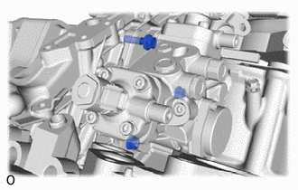
Loosen the bolt and 2 nuts to the tip of the thread.
- NOTICE:
-
-
To prevent the injection or supply pump assembly from falling off, do not completely remove the bolt and nut.
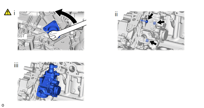
Install the handle to SST. Turn the handle in the counterclockwise direction to disconnect the supply pump assembly.
Remove the bolt and 2 nuts.
Remove the injection pump or supply pump assembly from the timing chain cover assembly.
- NOTICE:
-
SST holds the supply pump shaft sprocket, do not remove the SST until the injection or supply pump assembly is installed.
22100V 33.REMOVE INJECTION PUMP O-RING