1HZ ENGINE MECHANICAL ENGINE UNIT INSPECTION
PROCEDURE

 13525 1.INSPECT NO. 1 IDLE GEAR
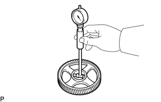
Using a cylinder gauge, measure the inside diameter of the No. 1 idle gear.
- Standard No. 1 idle gear inside diameter:
-
45.000 to 45.025 mm (1.7717 to 1.7726 in.)
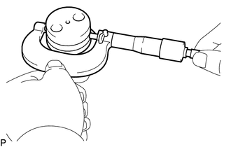
Using a micrometer, measure the diameter of the No. 1 idle gear shaft.
- Standard idle gear shaft diameter:
-
44.950 to 44.975 mm (1.7697 to 1.7707 in.)
Subtract the No. 1 idle gear shaft diameter measurement from the No. 1 idle gear inside diameter measurement.
- Standard oil clearance:
-
0.025 to 0.075 mm (0.000984 to 0.00295 in.)
- Maximum oil clearance:
-
0.20 mm (0.00787 in.)
If the oil clearance is more than the maximum, replace the No. 1 idle gear and No. 1 idle gear shaft.
13613D 2.INSPECT RADIAL BALL BEARING
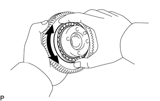
Check that radial ball bearing is not rough or worn.
If necessary, replace the radial ball bearing.
Click hereEngine / Hybrid System>1HZ (ENGINE MECHANICAL)>ENGINE UNIT>REPLACEMENT
3.CHECK BACKLASH OF TIMING GEARS
Using a dial indicator, measure the backlash.
- Standard gear backlash:
-
0.05 to 0.15 mm (0.00197 to 0.00591 in.)
- Maximum gear backlash:
-
0.30 mm (0.0118 in.)
If the gear backlash is more than the maximum, replace the gears as a set.
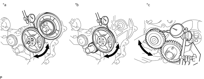
| *a | Injection Pump Drive Gear x No. 1 Idle Gear | *b | Crankshaft Timing Gear or Sprocket x No. 1 Idle Gear |
| *c | Oil Pump x Drive Shaft Pump Gear | - | - |
11101A 4.INSPECT CYLINDER HEAD SET BOLT
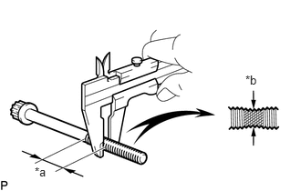
| *a | Measuring Point |
| *b | Elongated Thread |
Using a vernier caliper, measure the minimum diameter of the elongated thread at the measuring point.
- Standard diameter:
-
10.800 to 11.000 mm (0.425 to 0.433 in.)
- Minimum diameter:
-
10.550 mm (0.415 in.)
If the diameter is less than the minimum, replace the cylinder head set bolt.
13511 5.INSPECT CAMSHAFT
Inspect the camshaft runout.
Place the camshaft on V-blocks.
Using a dial indicator, measure the circle runout at the center journal.
- Maximum runout:
-
0.10 mm (0.00394 in.)
If the runout is more than the maximum, replace the camshaft.
Inspect the cam lobe height.
Using a micrometer, measure the cam lobe height.
- Standard Cam Lobe Height:
-
Item Specified Condition Intake 55.090 to 55.110 mm (2.1689 to 2.1697 in.) Exhaust 55.940 to 55.960 mm (2.2024 to 2.2031 in.)
- Minimum Cam Lobe Height:
-
Item Specified Condition Intake 54.59 mm (2.1492 in.) Exhaust 55.44 mm (2.1827 in.)
If the cam lobe height is less than the minimum, replace the camshaft.
Inspect the diameter of the camshaft journal.
Using a micrometer, measure the diameter of the camshaft journal diameter.
- Standard Diameter:
-
Item Specified Condition No. 1 journal 34.969 to 34.985 mm (1.3767 to 1.3774 in.) Others journal 27.986 to 27.988 mm (1.1018 to 1.1019 in.)
If the journal diameter is not as specified, check the oil clearance.
Inspect the camshaft bearings.
Check the camshaft bearings for flaking and scoring.
If the camshaft bearings are damaged, replace the camshaft bearings.
6.INSPECT CAMSHAFT OIL CLEARANCE
Clean the bearing caps and journals.
Check the bearings for flaking and scoring.
If the bearings are damaged, replace the bearing caps and cylinder head sub-assembly as a set.
Place the camshaft on the cylinder head.
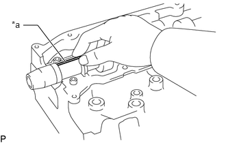
| *a | Plastigage |
Lay a strip of Plastigage across each of the journals.
Install the camshaft bearing caps.
Click hereEngine / Hybrid System>1HZ (ENGINE MECHANICAL)>CAMSHAFT>INSTALLATION
- NOTICE:
-
Do not turn the camshaft.
Remove the camshaft bearing caps.
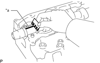
| *a | Plastigage |
Measure the Plastigage at its widest point.
- Standard Oil Clearance:
-
Item Specified Condition No. 1 journal 0.022 to 0.074 mm (0.000866 to 0.00291 in.) Other journals 0.030 to 0.066 mm (0.00118 to 0.00260 in.)
- Maximum oil clearance:
-
0.10 mm (0.00394 in.)
If the oil clearance is more than the maximum, replace the camshaft bearings and camshaft. If necessary, replace the bearing caps and cylinder head sub-assembly as a set.
Completely remove the Plastigage.
Remove the camshaft.
7.INSPECT CAMSHAFT THRUST CLEARANCE
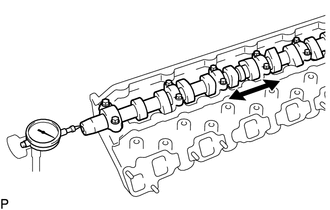
Check the thrust clearance.
Install the camshaft.
Click hereEngine / Hybrid System>1HZ (ENGINE MECHANICAL)>CAMSHAFT>INSTALLATION
Using a dial indicator, measure the thrust clearance while moving the camshaft back and forth.
- Standard thrust clearance:
-
0.10 to 0.20 mm (0.00394 to 0.00787 in.)
- Maximum thrust clearance:
-
0.30 mm (0.0118 in.)
If the thrust clearance is more than the maximum, replace the camshaft thrust plate. If necessary, replace the camshaft.
8.INSPECT VALVE LIFTERS AND LIFTER BORES
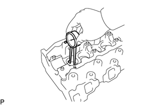
Using a caliper gauge, measure the lifter bore diameter of the cylinder head sub-assembly.
- Standard valve lifter bore diameter:
-
40.960 to 40.980 mm (1.6126 to 1.6134 in.)
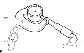
Using a micrometer, measure the valve lifter diameter.
- Standard valve lifter diameter:
-
40.892 to 40.902 mm (1.6099 to 1.6103 in.)
Subtract the valve lifter diameter measurement from the valve lifter bore diameter measurement.
- Standard oil clearance:
-
0.058 to 0.088 mm (0.00228 to 0.00346 in.)
- Maximum oil clearance:
-
0.10 mm (0.00394 in.)
If the oil clearance is more than the maximum, replace the valve lifter. If necessary, replace the cylinder head sub-assembly.
17111 9.INSPECT INTAKE MANIFOLD
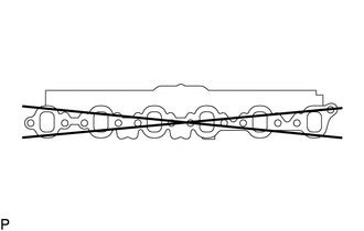
Using a precision straightedge and feeler gauge, measure the surface that contact the cylinder head sub-assembly for warpage.
- Maximum warpage:
-
0.40 mm (0.0157 in.)
If the warpage is more than the maximum, replace the intake manifold.
17141 10.INSPECT EXHAUST MANIFOLD
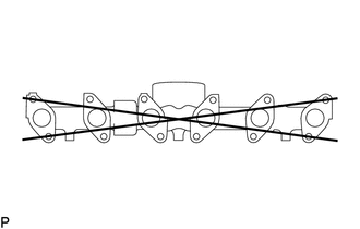
Using a precision straightedge and feeler gauge, measure the surface that contact the cylinder head sub-assembly for warpage.
- Maximum warpage:
-
0.40 mm (0.0157 in.)
If the warpage is more than the maximum, replace the exhaust manifold.