1VD-FTV EMISSION CONTROL EMISSION CONTROL SYSTEM(w/o DPF) ON-VEHICLE INSPECTION
CAUTION / NOTICE / HINT
- HINT:
-
In a malfunction where the EGR system is always on, black or white smoke may be emitted from the exhaust pipe.
PROCEDURE

 1.CHECK SEATING OF EGR VALVE
Start the engine, and then check that the engine starts and runs at idle.
2.CHECK ENGINE CONDITION
Connect the GTS to the DLC3.
Start the engine, then run it at idle.
Turn the GTS on.
Warm up the engine.
- HINT:
-
The coolant temperature should be between 75°C (167°F) and 90°C (194°F).
Enter the following menus: Powertrain / Engine and ECT / Data List / Actual EGR Valve Pos. or Actual EGR Valve Pos. #2.
- Powertrain > Engine and ECT > Data List
-
Tester Display Actual EGR Valve Pos. Actual EGR Valve Pos. #2 - 50003 61 578,579
Check that the value of the EGR angle is within the specification.
- Standard:
-
Engine Condition EGR Valve Opening Angle Expressed as Percentage During idling 0 to 83%
If the result is not as specified, refer to the EGR valve inspection procedures.
Click hereEngine / Hybrid System>1VD-FTV (EMISSION CONTROL)>EGR VALVE (w/o DPF)>INSPECTION
Turn the ignition switch off.
3.CHECK EGR VALVE OPERATION
Turn the ignition switch to ON.
Turn the GTS on.
Enter the following menus: Powertrain / Engine and ECT / Active Test / Control the EGR step position or Control the EGR step position #2.
- Powertrain > Engine and ECT > Active Test
-
Tester Display Control the EGR Step Position - 50004 61 95
- Powertrain > Engine and ECT > Active Test
-
Tester Display Control the EGR Step Position #2 - 50004 61 158
Check the Data List / Actual EGR Valve Pos. or Actual EGR Valve Pos. #2 reading.
- Powertrain > Engine and ECT > Data List
-
Tester Display Actual EGR Valve Pos. Actual EGR Valve Pos. #2 - 50003 61 578,579
- HINT:
-
Make sure the EGR valve opening angle changes according to the Active Test operation.
- Standard Percentage:
-
Control Range Condition Specified Condition Active Test performed (Set EGR position to 100%) EGR Valve Angle: 73 to 100% Active Test performed (Set EGR position to 0%) EGR Valve Angle: 0 to 27%
If the result is not as specified, refer to DTC P0400.
Click hereEngine / Hybrid System>1VD-FTV (ENGINE CONTROL)>ECD SYSTEM>P0400
4.CHECK MAF AMOUNT
- HINT:
-
·
While idling the engine, the EGR system operation can be checked by forcefully operating the EGR valve and checking the change in the MAF amount.
·During normal idling of the engine, the EGR valve is approximately 60% open.
·If the EGR valve is completely closed, the MAF amount increases.
Start the engine, then run it at idle.
Warm up the engine.
- HINT:
-
The coolant temperature should be between 75°C (167°F) and 90°C (194°F).
Turn the GTS on.
Enter the following menus: Powertrain / Engine and ECT / Data List / MAF.
- Powertrain > Engine and ECT > Data List
-
Tester Display MAF - 50003 61 319
Check the MAF reading.
- HINT:
-
When the EGR valve connector of bank 1 or bank 2 is disconnected, the EGR valve of bank 1 and bank 2 are fully closed by the fail-safe function.
- Standard:
-
Engine Condition Active Test Condition MAF Reading Idling Normal condition
(Active Test not performed)6.1 to 26.5 g/sec. EGR valve connector is disconnected
(Bank 1 and 2 are fully closed)14.2 to 26.5 g/sec.
- HINT:
-
·
If the MAF reading is out of the standard range for either "EGR valve connector is disconnected" or "Normal condition", replace the EGR valve.
·If the MAF reading is out of the standard range for both "EGR valve connector is disconnected" and "Normal condition", check the mass air flow meter. If any defects are found, replace the mass air flow meter, and then check the operation of the EGR valve.
Enter the following menus: Powertrain / Engine and ECT / Active Test / Control the EGR step position or Control the EGR step position #2.
- Powertrain > Engine and ECT > Active Test
-
Tester Display Control the EGR Step Position - 50004 61 95
- Powertrain > Engine and ECT > Active Test
-
Tester Display Control the EGR Step Position #2 - 50004 61 158
- HINT:
-
·
In the Active Test, the EGR valve of bank 1 and bank 2 cannot be operated at the same time.
·In the Active Test, the change in the MAF amount is difficult to check because the EGR valve can only be operated one bank at a time. Therefore, use the value below as a reference and check that the MAF amount changes.
- Standard (reference):
-
Engine Condition Active Test Condition MAF Reading Idling Active Test performed (Set EGR position to 0%) Air flow amount changes
(Approximately 7.8 to 26.5 g/sec.)
5.VISUALLY INSPECT HOSES, CONNECTIONS AND GASKETS
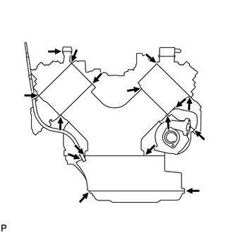
Visually check that the hoses, connections and gaskets have no cracks, leaks or damage.
- NOTICE:
-
·
Detachment or other problems with the engine oil dipstick, filler cap, PCV hose and other components may cause the engine to run improperly.
-
·
Air suction caused by disconnections, looseness or cracks in the parts of the air induction system between the throttle body and cylinder head will cause engine failure or engine malfunctions.
If the result is not as specified, replace parts as necessary.