1VD-FTV FUEL FUEL INJECTOR(w/o DPF) REMOVAL
PROCEDURE

 1.CHECK INJECTOR COMPENSATION CODE
Check that the injector compensation code registered in the injector assembly installed on each cylinder matches the one registered in the engine ECM.
Click hereEngine / Hybrid System>1VD-FTV (ENGINE CONTROL)>ECD SYSTEM>REGISTRATION
If the code does not match, follow the procedures below to correct the registration details and recheck the symptom.
Correct the registration details by following the procedures in "Register Injector Compensation Code".
Click hereEngine / Hybrid System>1VD-FTV (ENGINE CONTROL)>ECD SYSTEM>REGISTRATION
After correcting the registration details, check if the symptom that occurred when the vehicle was brought in recurs.
- HINT:
-
If it does not occur, the symptom may be caused by errors in the injector compensation code registration.
2. PRECAUTION
- NOTICE:
-
After turning the ignition switch off, watching time may be required before disconnecting the cable from the battery terminal. Therefore, make sure to read the disconnecting the cable from the battery terminal notice before proceeding with work.
-
Click hereGeneral>INTRODUCTION>REPAIR INSTRUCTION>PRECAUTION
3.DISCONNECT CABLE FROM NEGATIVE BATTERY TERMINAL
4.DRAIN ENGINE COOLANT
17940D 5.REMOVE INTERCOOLER ASSEMBLY
26100G 6.REMOVE DIESEL THROTTLE BODY ASSEMBLY
12142 7.REMOVE NO. 2 ENGINE OIL LEVEL DIPSTICK GUIDE
16267 8.DISCONNECT NO. 2 WATER BY-PASS HOSE AND NO. 3 WATER BY-PASS HOSE
23284A 9.DISCONNECT NO. 5 FUEL HOSE
23804D 10.REMOVE NO. 4 FUEL PIPE SUB-ASSEMBLY
44769 11.DISCONNECT VACUUM RESERVOIR CONNECT TUBE
82122 12.DISCONNECT NO. 2 ENGINE WIRE
44761 13.REMOVE VACUUM PUMP TO CONNECTOR TUBE
25850 14.REMOVE VACUUM REGULATING VALVE
16288 15.REMOVE NO. 4 WATER BY-PASS PIPE
16278 16.REMOVE NO. 2 WATER BY-PASS PIPE
82121 17.DISCONNECT ENGINE WIRE
23265 18.REMOVE NO. 1 GAS FILTER
17947B 19.REMOVE NO. 3 INTERCOOLER SUPPORT BRACKET
20.REMOVE INJECTION PIPE RH
21.REMOVE INJECTION PIPE LH
23706 22.REMOVE NO. 6 INJECTION PIPE SUB-ASSEMBLY
23239D 23.REMOVE NO. 1 FUEL HOSE
23805B 24.REMOVE NO. 5 FUEL PIPE SUB-ASSEMBLY
23810A 25.REMOVE COMMON RAIL LH
23801L 26.REMOVE FUEL FILTER TO INJECTION PUMP FUEL PIPE SUB-ASSEMBLY
23681D 27.REMOVE NOZZLE HOLDER SEAL RH
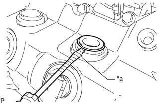
| *a | Protective Tape |
Using a small screwdriver, remove the 4 nozzle holder seal RH by prying the portion between each nozzle holder seal RH and the cutout part of the cylinder head cover sub-assembly RH.
- HINT:
-
Tape the screwdriver tip before use.
23681E 28.REMOVE NOZZLE HOLDER SEAL LH
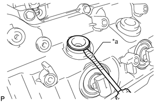
| *a | Protective Tape |
Using a small screwdriver, remove the 4 nozzle holder seal LH by prying the portion between each nozzle holder seal LH and the cutout part of the cylinder head cover sub-assembly LH.
- HINT:
-
Tape the screwdriver tip before use.
12270 29.REMOVE OIL SEPARATOR ASSEMBLY
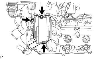
Slide the clamp and disconnect the ventilation hose from the oil separator assembly.
Remove the 3 bolts, oil separator assembly and gasket.
11202 30.REMOVE CYLINDER HEAD COVER SUB-ASSEMBLY LH
Slide the clamp and disconnect the No. 3 ventilation hose from the cylinder head cover sub-assembly LH.
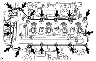
Remove the 17 bolts, cylinder head cover sub-assembly LH and cylinder head cover gasket.
11201 31.REMOVE CYLINDER HEAD COVER SUB-ASSEMBLY RH
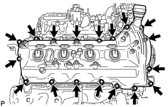
Remove the 18 bolts, cylinder head cover sub-assembly RH and cylinder head cover gasket.
32.REMOVE FUEL INJECTOR RH
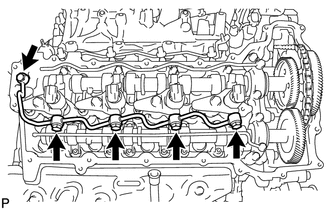
Remove the union bolt, 4 hollow screws, 5 gaskets and nozzle leakage pipe.
- NOTICE:
-
·
When removing the nozzle leakage pipe, place a cushion under the nozzle leakage pipe.
·Be careful not to deform or scratch the union seal surface.
·After removing the fuel pipe, put it in a plastic bag to prevent foreign matter from contaminating its injector inlet.
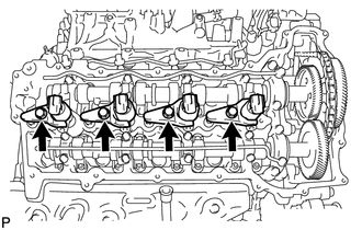
Remove the 4 bolts, 4 washers, 4 nozzle holder clamps and 4 fuel injector RH.
- HINT:
-
Arrange the fuel injector RH, nozzle holder clamps, washers and bolts in the correct order.
Remove the O-ring from each fuel injector RH.
Remove the 4 injection nozzle seats from the cylinder head sub-assembly RH.
33.REMOVE FUEL INJECTOR LH
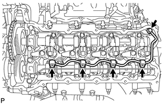
Remove the union bolt, 4 hollow screws, 5 gaskets and No. 2 nozzle leakage pipe.
- NOTICE:
-
·
When removing the No. 2 nozzle leakage pipe, place a cushion under the No. 2 nozzle leakage pipe.
·Be careful not to deform or scratch the union seal surface.
·After removing the fuel pipe, put it in a plastic bag to prevent foreign matter from contaminating its injector inlet.
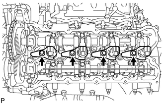
Remove the 4 bolts, 4 washers, 4 nozzle holder clamps and 4 fuel injector LH.
- HINT:
-
Arrange the fuel injector LH, nozzle holder clamps, washers and bolts in the correct order.
Remove the O-ring from each fuel injector LH.
Remove the 4 injection nozzle seats from the cylinder head sub-assembly LH.