1GR-FE INTAKE / EXHAUST EXHAUST MANIFOLD INSTALLATION
PROCEDURE

 89465 1.INSTALL HEATED OXYGEN SENSOR (for Bank 1 Sensor 2)
89467B 2.INSTALL AIR FUEL RATIO SENSOR (for Bank 1 Sensor 1)
17104 3.INSTALL EXHAUST MANIFOLD SUB-ASSEMBLY RH
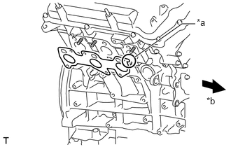
| *a | Oval Shape |
| *b | Front |
Install a new gasket to the cylinder head sub-assembly RH with the oval shape facing forward.
- NOTICE:
-
Make sure the gasket is installed facing the proper direction.
Install the exhaust manifold sub-assembly RH with 6 new nuts.
- Torque:
- 30 N*m (306 kgf*cm, 22 ft.*lbf)
Connect the air fuel ratio sensor (for Bank 1 Sensor 1) and heated oxygen sensor (for Bank 1 Sensor 2) connectors.
17118 4.INSTALL NO. 1 MANIFOLD STAY
Install the No. 1 manifold stay with the 3 bolts.
- Torque:
- 40 N*m (408 kgf*cm, 30 ft.*lbf)
89465A 5.INSTALL HEATED OXYGEN SENSOR (for Bank 2 Sensor 2)
89467C 6.INSTALL AIR FUEL RATIO SENSOR (for Bank 2 Sensor 1)
17105 7.INSTALL EXHAUST MANIFOLD SUB-ASSEMBLY LH
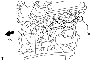
| *a | Oval Shape |
| *b | Front |
Install a new gasket to the cylinder head sub-assembly LH with the oval shape facing rearward.
- NOTICE:
-
Make sure the gasket is installed facing the proper direction.
Install the exhaust manifold sub-assembly LH with 6 new nuts.
- Torque:
- 30 N*m (306 kgf*cm, 22 ft.*lbf)
Connect the air fuel ratio sensor (for Bank 2 Sensor 1) and heated oxygen sensor (for Bank 2 Sensor 2) connectors.
17119 8.INSTALL NO. 2 MANIFOLD STAY
Install the No. 2 manifold stay with the 3 bolts.
- Torque:
- 40 N*m (408 kgf*cm, 30 ft.*lbf)
53736 9.INSTALL FRONT FENDER APRON SEAL RH
Attach the 11 clips and install the front fender apron seal RH.
53737B 10.INSTALL FRONT FENDER APRON SEAL LH
Attach the 11 clips and install the front fender apron seal LH.
17410 11.INSTALL FRONT EXHAUST PIPE SUB-ASSEMBLY
for Model Code #J71, #76 Series
for Model Code #J78, #79 Series
12.INSPECT FOR EXHAUST GAS LEAK
If gas is leaking, tighten the areas necessary to stop the leak. Replace damaged parts as necessary.