1GR-FE ENGINE MECHANICAL ENGINE UNIT INSTALLATION
PROCEDURE

 13453 1.INSTALL FLYWHEEL RING GEAR
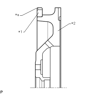
| *1 | Flywheel Ring Gear |
| *2 | Flywheel Sub-assembly |
| *a | Chamfer |
Using a torch, heat the flywheel ring gear evenly to approximately 200°C (392°F).
- NOTICE:
-
Be careful not to overheat the flywheel ring gear.
Using a brass bar, tap the flywheel ring gear onto the flywheel sub-assembly with its chamfered gear teeth facing the cylinder block sub-assembly.
- NOTICE:
-
After installing, allow the flywheel ring gear to cool before handling.
16603 2.INSTALL NO. 1 IDLER PULLEY SUB-ASSEMBLY
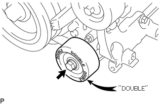
Install the No. 1 idler pulley sub-assembly with the bolt.
- Torque:
- 54 N*m (551 kgf*cm, 40 ft.*lbf)
- NOTICE:
-
·
Do not mistakenly install the No. 2 idler pulley sub-assembly instead of the No. 1 idler pulley sub-assembly.
·The No. 1 idler pulley sub-assembly has a "DOUBLE" mark.
16604 3.INSTALL NO. 2 IDLER PULLEY SUB-ASSEMBLY
for Cover Separate Type:
Install the 2 idler pulley cover plates, 2 No. 2 idler pulley cover plates and 2 No. 2 idler pulley sub-assemblies with the 2 bolts.
- Torque:
- 54 N*m (551 kgf*cm, 40 ft.*lbf)
for Cover Integrated Type:
Install the 2 No. 2 idler pulley sub-assemblies with the 2 bolts.
- Torque:
- 54 N*m (551 kgf*cm, 40 ft.*lbf)
12315 4.INSTALL FRONT NO. 1 ENGINE MOUNTING BRACKET LH
Install the front No. 1 engine mounting bracket LH with the 3 bolts.
- Torque:
- 48 N*m (489 kgf*cm, 35 ft.*lbf)
12311 5.INSTALL FRONT NO. 1 ENGINE MOUNTING BRACKET RH
Install the front No. 1 engine mounting bracket RH with the 4 bolts.
- Torque:
- 48 N*m (489 kgf*cm, 35 ft.*lbf)
16620 6.INSTALL V-RIBBED BELT TENSIONER ASSEMBLY
Temporarily install the V-ribbed belt tensioner assembly with the 5 bolts.
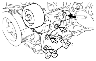

|
Bolt A |

|
Bolt B |
Tighten bolts 1 and 2 in numerical order.
- Torque:
- 36 N*m (367 kgf*cm, 27 ft.*lbf)
Tighten the other bolts.
- Torque:
- 36 N*m (367 kgf*cm, 27 ft.*lbf)
- Standard Bolt Length:
-
Item Specified Condition Bolt A 70 mm (2.76 in.) Bolt B 33 mm (1.30 in.)
19500 7.INSTALL IGNITION COIL ASSEMBLY
8.INSTALL ENGINE WIRE
Install the engine wire.
17111 9.INSTALL INTAKE MANIFOLD
23250 10.INSTALL FUEL INJECTOR ASSEMBLY
23807 11.INSTALL FUEL DELIVERY PIPE SUB-ASSEMBLY
23801P 12.INSTALL NO. 1 FUEL PIPE SUB-ASSEMBLY AND NO. 2 FUEL PIPE SUB-ASSEMBLY
87246A 13.INSTALL OUTLET HEATER WATER HOSE
Install the outlet heater water hose, and slide the hose clamp to secure the hose.
87209 14.INSTALL WATER HOSE SUB-ASSEMBLY
Install the water hose sub-assembly with the nut.
- Torque:
- 5.0 N*m (51 kgf*cm, 44 in.*lbf)
Slide the hose clamp to secure the water hose sub-assembly.