1GR-FE LUBRICATION OIL PUMP INSTALLATION
PROCEDURE

 11302 1.INSTALL TIMING CHAIN COVER SUB-ASSEMBLY
11301C 2.INSTALL FRONT CRANKSHAFT OIL SEAL
15609 3.INSTALL OIL FILTER BRACKET SUB-ASSEMBLY
16323 4.INSTALL WATER INLET HOUSING
15777 5.INSTALL OIL COOLER HOSE
15778 6.INSTALL NO. 2 OIL COOLER HOSE
12101 7.INSTALL OIL PAN SUB-ASSEMBLY
Remove any old packing (FIPG material) and be careful not to drop any oil on the contact surfaces of the cylinder block, rear oil seal retainer and oil pan sub-assembly.
Install a new O-ring to the timing chain cover assembly.
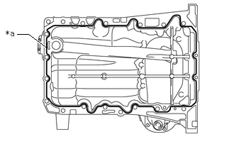
| *a | Seal Packing |
Apply seal packing in a continuous line as shown in the illustration.
- Seal packing:
-
Toyota Genuine Seal Packing Black, Three Bond 1207B or equivalent
- Standard seal diameter:
-
3.0 to 4.0 mm (0.118 to 0.157 in.)
- NOTICE:
-
·
Remove any oil from the contact surface.
·Install the oil pan sub-assembly within 3 minutes after applying seal packing.
·Do not start the engine for at least 2 hours after installing.
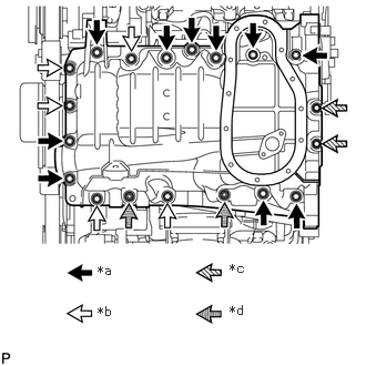
| *a | Bolt A |
| *b | Bolt B |
| *c | Bolt C |
| *d | Nut |
Install the oil pan sub-assembly with the 17 bolts (A, B and C) and 2 nuts. Tighten the bolts and nuts uniformly in several steps.
- Torque:
- for bolt A, B and nut : 21 N*m (214 kgf*cm, 15 ft.*lbf)
- for bolt C : 10 N*m (102 kgf*cm, 7 ft.*lbf)
| Item | Quantity | Length |
|---|---|---|
| Bolt A | 10 | 45 mm (1.77 in.) |
| Bolt B | 5 | 25 mm (0.984 in.) |
| Bolt C | 2 | 14 mm (0.551 in.) |
Install the 4 bolts.
- Torque:
- 37.3 N*m (380 kgf*cm, 28 ft.*lbf)
11361J 8.INSTALL UNDER FLYWHEEL HOUSING COVER
Install the under flywheel housing cover.
15104 9.INSTALL OIL STRAINER SUB-ASSEMBLY
12102A 10.INSTALL NO. 2 OIL PAN SUB-ASSEMBLY
13471 11.INSTALL CRANKSHAFT PULLEY
16603 12.INSTALL NO. 1 IDLER PULLEY SUB-ASSEMBLY
16604 13.INSTALL NO. 2 IDLER PULLEY SUB-ASSEMBLY
16620 14.INSTALL V-RIBBED BELT TENSIONER ASSEMBLY
16356 15.INSTALL REAR WATER BY-PASS JOINT
Apply soapy water to a new O-ring and install it to the water outlet pipe. Then install 2 new gaskets to the water ports LH and RH.
Install the rear water by-pass joint with the 2 bolts and 4 nuts.
- Torque:
- for bolt : 10 N*m (102 kgf*cm, 7 ft.*lbf)
- for nut : 9.0 N*m (92 kgf*cm, 80 in.*lbf)
Connect the engine coolant temperature sensor connector.
11202 16.INSTALL CYLINDER HEAD COVER SUB-ASSEMBLY LH
11201 17.INSTALL CYLINDER HEAD COVER SUB-ASSEMBLY
18.CONNECT WIRE HARNESS
19.CONNECT CLUTCH TUBE
Connect the clutch tube with the bolt.
- Torque:
- 8.0 N*m (82 kgf*cm, 71 in.*lbf)
87246A 20.INSTALL OUTLET HEATER WATER HOSE
Install the outlet heater water hose, and slide the 2 clamps to secure the hose.
87209 21.INSTALL WATER HOSE SUB-ASSEMBLY
Install the water hose sub-assembly with the bolt.
- Torque:
- 5.0 N*m (51 kgf*cm, 44 in.*lbf)
Connect the water hose sub-assembly, and slide the clamp to secure the hose.
87245A 22.INSTALL INLET HEATER WATER HOSE
Install the inlet heater water hose, and slide the 2 clamps to secure the hose.
15340 23.INSTALL CAMSHAFT TIMING OIL CONTROL VALVE ASSEMBLY LH
15330B 24.INSTALL CAMSHAFT TIMING OIL CONTROL VALVE ASSEMBLY RH
25.INSTALL VVT SENSOR (for Bank 2)
26.INSTALL VVT SENSOR (for Bank 1)
19500 27.INSTALL IGNITION COIL ASSEMBLY
23801P 28.INSTALL NO. 1 FUEL PIPE SUB-ASSEMBLY AND NO. 2 FUEL PIPE SUB-ASSEMBLY
Install the No. 1 fuel pipe sub-assembly and No. 2 fuel pipe sub-assembly with the 2 bolts.
- Torque:
- 9.0 N*m (92 kgf*cm, 80 in.*lbf)
Connect the No. 1 fuel pipe sub-assembly and No. 2 fuel pipe sub-assembly.
Click hereEngine / Hybrid System>1GR-FE (FUEL)>FUEL SYSTEM>PRECAUTION
Install the No. 1 fuel pipe clamp and 2 No. 2 fuel pipe clamps.
82127 29.CONNECT NO. 7 ENGINE WIRE
Connect the No. 7 engine wire with the bolt.
- Torque:
- 8.4 N*m (86 kgf*cm, 74 in.*lbf)
88712 30.CONNECT NO. 1 COOLER REFRIGERANT SUCTION HOSE (w/ Air Conditioning System)
for LHD:
Connect the No. 1 cooler refrigerant suction hose with the bolt.
- Torque:
- 9.5 N*m (97 kgf*cm, 84 in.*lbf)
44310 31.CONNECT VANE PUMP ASSEMBLY
27020 32.INSTALL GENERATOR ASSEMBLY
16631B 33.INSTALL IDLER PULLEY BRACKET (w/o Air Conditioning System)
Install the idler pulley bracket with the 3 bolts.
- Torque:
- 25 N*m (255 kgf*cm, 18 ft.*lbf)
88320 34.INSTALL COOLER COMPRESSOR ASSEMBLY (w/ Air Conditioning System)
16711 35.INSTALL FAN SHROUD
36.INSTALL EXHAUST MANIFOLD
17111 37.INSTALL INTAKE MANIFOLD
38.ADD ENGINE COOLANT
39.ADD ENGINE OIL
40.CHARGE AIR CONDITIONING SYSTEM WITH REFRIGERANT (w/ Air Conditioning System)
41.INSPECT FOR COOLANT LEAK
42.INSPECT FOR OIL LEAK
43.CHECK ENGINE OIL LEVEL
44.INSPECT FOR EXHAUST GAS LEAK
45.INSPECT FOR REFRIGERANT LEAK (w/ Air Conditioning System)
46.INSPECT IGNITION TIMING