BRAKE SYSTEM (OTHER) BRAKE PEDAL INSTALLATION
PROCEDURE

 47121 1.INSTALL BRAKE PEDAL PAD
Install the brake pedal pad to the brake pedal support assembly.
47110 2.INSTALL BRAKE PEDAL SUPPORT ASSEMBLY
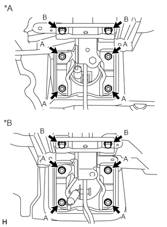
| *A | for LHD |
| *B | for RHD |
Install the support with the 4 nuts A and 2 bolts B.
- Torque:
- for nut A : 14.2 N*m (145 kgf*cm, 10 ft.*lbf)
- for bolt B : 19 N*m (194 kgf*cm, 14 ft.*lbf)
47264A 3.INSTALL PUSH ROD PIN
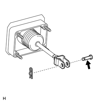

|
Lithium soap base glycol grease |
Apply a light coat of lithium soap base glycol grease to the push rod pin.
Install the push rod pin to the push rod clevis.
- NOTICE:
-
The push rod pin must be installed as shown in the illustration.
Install a new clip to the push rod pin.
- NOTICE:
-
The clip must be installed as shown in the illustration.
47101A 4.INSTALL BRAKE PEDAL RETURN SPRING
Install the brake pedal return spring to the brake pedal support assembly.
89780 5.INSTALL TRANSPONDER KEY ECU ASSEMBLY (w/ Engine Immobiliser System)
84340 6.INSTALL STOP LIGHT SWITCH ASSEMBLY
7.CHECK AND ADJUST BRAKE PEDAL