BF1B TRANSFER / 4WD / AWD TRANSFER SYSTEM INSPECTION
PROCEDURE

 1. TRANSFER SYSTEM
- NOTICE:
-
for Direct Shift Type·
w/ Dual Mode Automatic Locking Hub (AUTO Position):
To shift from H2 to H4, stop the vehicle and move the transfer shift lever.
·To shift from H4 to L4, stop the vehicle or reduce the vehicle speed to less than 8 km/h (5 mph). Then, release the accelerator pedal, depress the clutch pedal and move the transfer shift lever.
-
for Vacuum Shift Type·
w/ Dual Mode Automatic Locking Hub (AUTO Position):
To shift from H to H4, stop the vehicle and push the transmission control switch.
·To shift from H or H4 to L4, stop the vehicle or reduce the vehicle speed to less than 8 km/h (5 mph). Then, release the accelerator pedal, depress the clutch pedal and move the transfer shift lever.
·To shift from L4 to H4 or H, stop the vehicle or reduce the vehicle speed to less than 8 km/h (5 mph). Then, release the accelerator pedal, depress the clutch pedal and move the transfer shift lever.
2.INSPECT INDICATOR LIGHT
4WD Indicator Light (for Direct Shift Type):
Start the engine.
Move the transfer shift lever from the H2 position to the H4, L4 or N position.
Check that the 4WD indicator light illuminates.
- OK:
-
4WD indicator light comes on
If the result is not as specified, inspect the transfer indicator switch (4WD position) and four wheel drive control ECU (w/ Differential Lock).
If the system is normal, there may be a malfunction in the combination meter (Click hereVehicle Interior>METER / GAUGE / DISPLAY>METER / GAUGE SYSTEM>PROBLEM SYMPTOMS TABLE).
4WD Indicator Light (for Vacuum Shift Type):
Start the engine.
Push the transmission control switch.
Check that the 4WD indicator light illuminates.
- OK:
-
4WD indicator light comes on
If the result is not as specified, inspect the transfer indicator switch (4WD position), transmission control switch and four wheel drive control ECU(w/ Differential Lock).
If the system is normal, there may be a malfunction in the combination meter (Click hereVehicle Interior>METER / GAUGE / DISPLAY>METER / GAUGE SYSTEM>PROBLEM SYMPTOMS TABLE).
89533A 3.INSPECT NO. 2 4 WHEEL DRIVE CONTROL ECU (w/ Differential Lock)
Inspect the No. 2 4 wheel drive control ECU (power supply).
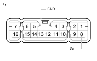
| *a | Component with harness connected (No. 2 4 Wheel Drive Control ECU) |
Measure the voltage according to the value(s) in the table below.
- Standard Voltage:
-
Tester Connection Switch Condition Specified Condition 8 (IG) - Body ground Ignition switch ON 11 to 14 V
If the result is not as specified, inspect the harness, fuse or connector.
If the harness or connector is malfunctioning, repair or replace the harness or connector.
If the harness or connector is normal, replace the No. 2 4 wheel drive control ECU (Click here Drivetrain>AXLE AND DIFFERENTIAL>DIFFERENTIAL LOCK ECU (w/ Differential Lock)>REMOVAL).
Measure the resistance according to the value(s) in the table below.
- Standard Resistance:
-
Tester Connection Condition Specified Condition 13 (GND) - Body ground Always Below 1 Ω
If the result is not as specified, repair or replace the harness or connector.
Inspect the No. 2 4 wheel drive control ECU (transfer indicator switch (4WD position)).
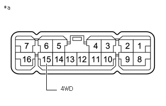
| *a | Component with harness connected (No. 2 4 Wheel Drive Control ECU) |
Measure the voltage according to the value(s) in the table below.
- Standard Voltage:
-
Tester Connection Condition Specified Condition 15 (4WD) - Body ground Ignition switch ON
Transfer position
H2 (for Direct Shift Type)
H (for Vacuum Shift Type)8 to 14 V Ignition switch ON
Transfer position H4Below 1 V Ignition switch ON
Transfer position N or L48 to 14 V
If the result is not as specified, check the power supply.
If the power supply is normal, inspect the transfer indicator switch (Click hereDrivetrain>BF1B (TRANSFER / 4WD / AWD)>TRANSFER INDICATOR SWITCH>INSPECTION).