BF1B TRANSFER / 4WD / AWD TRANSFER ASSEMBLY REASSEMBLY
CAUTION / NOTICE / HINT
- NOTICE:
-
·
When using a vise, place aluminum plates between the part and vise.
·When using a vise, do not overtighten it.
PROCEDURE

 36307A 1.INSTALL HIGH AND LOW SHIFT INNER LEVER OIL SEAL
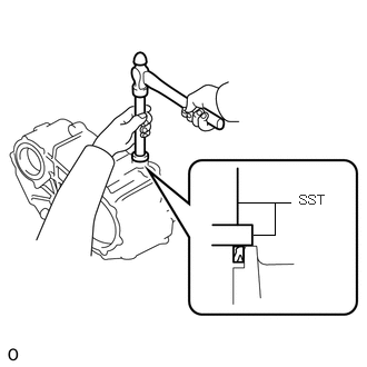
Using SST and a hammer, install a new high and low shift inner lever oil seal.
- SST
-
09950-60010 (09951-00200)
09950-70010 (09951-07100)
Apply MP grease to the high and low shift inner lever oil seal lip.
36362 2.INSTALL TRANSFER HIGH AND LOW SHIFT OUTER LEVER
Install the high and low shift inner lever sub-assembly.
Install the transfer high and low shift outer lever and washer.
Install the spring washer and 2 plate washers with the bolt and nut.
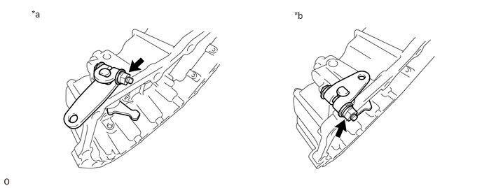
| *a | for Direct Shift Type | *b | for Vacuum Shift Type |
- Torque:
- 19.6 N*m (200 kgf*cm, 14 ft.*lbf)
- NOTICE:
-
Be careful not to damage the high and low shift inner lever oil seal lip.
36422 3.INSTALL TRANSFER DIAPHRAGM PLATE (for Vacuum Shift Type)
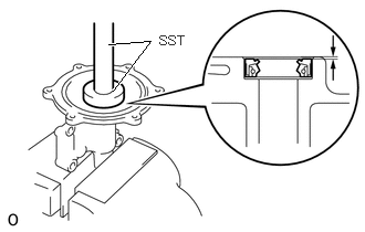
Using SST and a hammer, install a new diaphragm push rod type T seal.
- SST
-
09950-60010 (09951-00250)
09950-70010 (09951-07100)
- Standard depth:
-
0 to 1.0 mm (0 to 0.393 in.)
Apply MP grease to the diaphragm push rod type T seal lip.
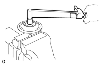
Install a new diaphragm push rod O-ring, 2 plate washers, 2 transfer diaphragm plates and diaphragm cylinder diaphragm to the diaphragm push rod with the nut.
- Torque:
- 36.75 N*m (375 kgf*cm, 27 ft.*lbf)
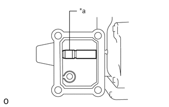
| *a | Cutout Portion |
Install the cutout portion of the diaphragm push rod into the open part of the diaphragm cylinder body.
4.INSTALL DIAPHRAGM CYLINDER COVER (for Vacuum Shift Type)
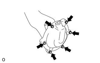
Install the diaphragm cylinder cover to the diaphragm cylinder with the 6 bolts.
- Torque:
- 7.35 N*m (75 kgf*cm, 65 in.*lbf)
36486 5.INSTALL SUCTION TUBE (for Vacuum Shift Type)
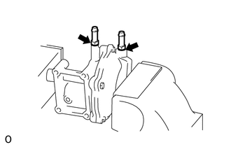
Install the 2 suction tubes with 2 new gaskets.
- Torque:
- 36.75 N*m (375 kgf*cm, 27 ft.*lbf)
36234A 6.INSTALL FRONT TRANSFER OUTPUT SHAFT BEARING
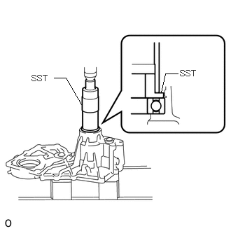
Using a press, press in a new front transfer output shaft bearing.
- SST
-
09316-60011 (09316-00011, 09316-00021)
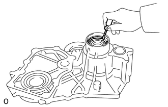
Using a screwdriver, install the front transfer output shaft bearing snap ring.
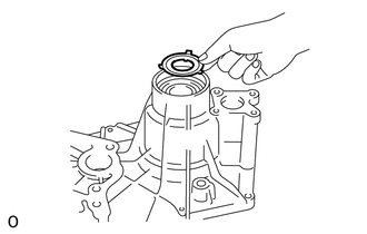
Install the No. 2 transfer oil receiver.
36134A 7.INSTALL FRONT OUTPUT SHAFT BEARING RETAINER OIL SEAL
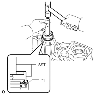
| *1 | Front Output Shaft Bearing Retainer Oil Seal |
Using SST and a hammer, install a new front output shaft bearing retainer oil seal.
- SST
-
09608-32010
09950-70010 (09951-07100)
Apply MP grease to the front output shaft bearing retainer oil seal lip.
36313J 8.INSTALL FRONT TRANSFER DRIVE SHIFT SHAFT OIL SEAL (for Direct Shift Type)
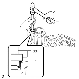
| *1 | Front Transfer Drive Shift Shaft Oil Seal |
Using SST and a hammer, install a new front transfer drive shift shaft oil seal.
- SST
-
09950-60010 (09951-00400)
09950-70010 (09951-07100)
Apply MP grease to the front transfer drive shift shaft oil seal lip.
36111B 9.INSTALL TRANSFER CASE OIL SEAL
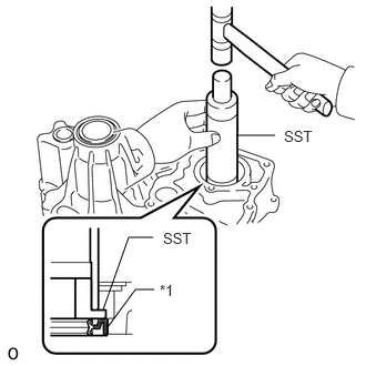
| *1 | Transfer Case Oil Seal |
Using SST and a hammer, install a new transfer case oil seal.
- SST
-
09316-60011 (09316-00011, 09316-00021)
Apply MP grease to the transfer case oil seal lip.
36234 10.INSTALL FRONT TRANSFER OUTPUT SHAFT
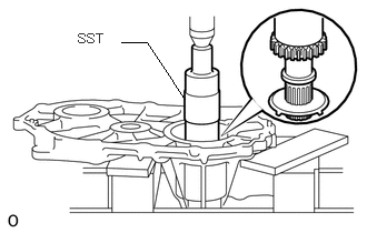
Using SST and a press, press in the front transfer output shaft to the front transfer case.
- SST
-
09316-60011 (09316-00011)
36104 11.INSTALL TRANSFER OUTPUT SHAFT COMPANION FLANGE
Install the transfer output shaft companion flange and transfer output shaft plate washer.
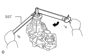
| *a | Turn |
| *b | Hold |
Using SST to hold the transfer output shaft companion flange, install a new transfer output shaft nut.
- SST
-
09330-00021
- Torque:
- 127.4 N*m (1299 kgf*cm, 94 ft.*lbf)
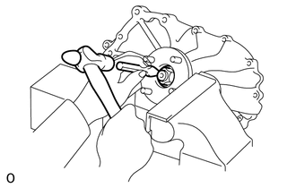
Using a chisel and hammer, stake the transfer output shaft nut.
- NOTICE:
-
·
Securely stake the shaft to the nut groove.
·Be careful not to damage the parts around the nut.
·Do not apply excessive force to the shaft.
36212F 12.INSTALL FRONT TRANSFER INPUT SHAFT RADIAL BALL BEARING
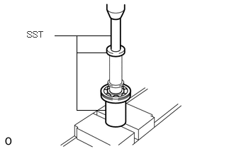
Using SST and a press, press in the front transfer input shaft radial ball bearing to the transfer input shaft.
- SST
-
09523-36010
09950-60010 (09951-00500)
09950-70010 (09951-07100)
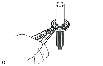
Using a snap ring expander, install the snap ring to the transfer input shaft.
36211 13.INSTALL TRANSFER INPUT SHAFT
Install a new O-ring to the transfer input shaft.
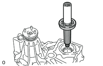
Install the transfer input shaft to the front transfer case.
36311 14.INSTALL NO. 1 TRANSFER GEAR SHIFT FORK
for Direct Shift Type:
Install the No. 1 transfer gear shift fork to the front transfer drive shift shaft.
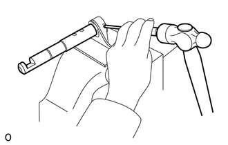
Using a pin punch and hammer, tap in the transfer shift fork slotted spring pin to the No. 1 transfer gear shift fork.
for Vacuum Shift Type:
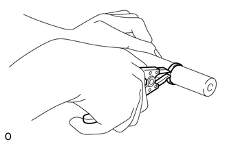
Using snap ring pliers, install the snap ring to the front transfer drive shift shaft.
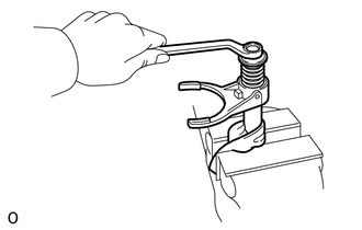
Install the plate washer, front transfer drive shift shaft compression spring and No. 1 transfer gear shift fork to the front transfer drive shift shaft with the bolt.
- Torque:
- 18.13 N*m (185 kgf*cm, 13 ft.*lbf)
36236 15.INSTALL FRONT DRIVE CLUTCH SLEEVE
Install the front drive clutch sleeve with the No. 1 transfer gear shift fork.
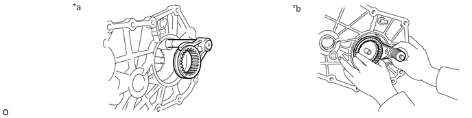
| *a | for Direct Shift Type | *b | for Vacuum Shift Type |
36318 16.INSTALL FRONT TRANSFER DRIVE SHIFT BOOT (for Direct Shift Type)
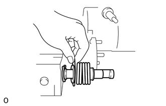
Install the front transfer drive shift boot to the front transfer case.
36343A 17.INSTALL FRONT VACUUM MAGNET TYPE DRIVE SHIFT LINK LEVER SHOE (for Vacuum Shift Type)
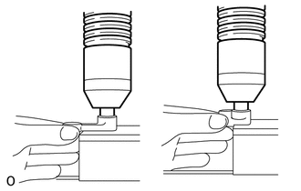
Using a press, press in the 2 front vacuum magnet type drive shift link lever shoes to the front drive shift link lever.
18.INSTALL DIAPHRAGM CYLINDER BODY (for Vacuum Shift Type)
Clean and degrease the bolt and the installation hole.
Apply adhesive to 2 or 3 threads on the ends of the bolt.
- Adhesive:
-
Toyota Genuine Adhesive 1324, Three Bond 1324 or equivalent
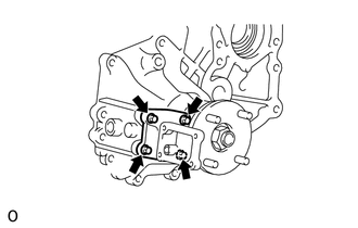
Install a new transfer shift shaft guide gasket and diaphragm cylinder body with the 4 bolts.
- Torque:
- 18.13 N*m (185 kgf*cm, 13 ft.*lbf)
36337 19.INSTALL FRONT DRIVE SHIFT LINK LEVER (for Vacuum Shift Type)
Apply MP grease to the 2 front vacuum magnet type drive shift link lever shoes and front drive shift link lever straight pin.
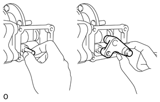
Install the 2 vacuum magnet type front drive shift link lever shoes and front drive shift link lever straight pin.
36410 20.INSTALL DIAPHRAGM CYLINDER ASSEMBLY (for Vacuum Shift Type)
Clean and degrease the bolt and the installation hole.
Apply adhesive to 2 or 3 threads on the ends of the bolt.
- Adhesive:
-
Toyota Genuine Adhesive 1324, Three Bond 1324 or equivalent
Install a new diaphragm cylinder gasket and diaphragm cylinder assembly with the 4 bolts.
- Torque:
- 18.13 N*m (185 kgf*cm, 13 ft.*lbf)
33404E 21.INSTALL SPEEDOMETER SHAFT SLEEVE OIL SEAL (w/o ABS)
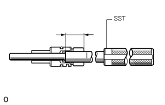
Using SST, install a new speedometer shaft sleeve oil seal.
- SST
-
09201-10000 (09201-01080)
- Standard oil seal depth:
-
20 mm (0.787 in.)
36132A 22.INSTALL OUTPUT SHAFT RETAINER OIL SEAL
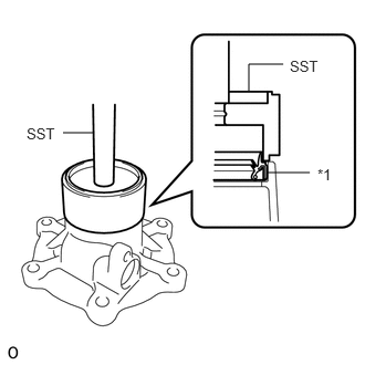
| *1 | Output Shaft Retainer Oil Seal |
Using SST and a hammer, install a new output shaft retainer oil seal.
- SST
-
09316-10010
09950-70010 (09951-07100)
Apply MP grease to the output shaft retainer oil seal lip.
36231C 23.INSTALL TRANSFER OUTPUT SHAFT TAPER ROLLER BEARING
for High Gear Side:
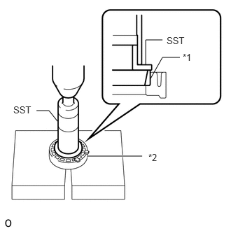
| *1 | Transfer Output Shaft Taper Roller Bearing (Outer Race) |
| *2 | Front Output Shaft Bearing Retainer |
Using SST and a press, press in the transfer output shaft taper roller bearing (outer race) to the front output shaft bearing retainer.
- SST
-
09316-60011 (09316-00011, 09316-00041)
- HINT:
-
Replace both the outer race and bearing as a set.
for Low Gear Side:
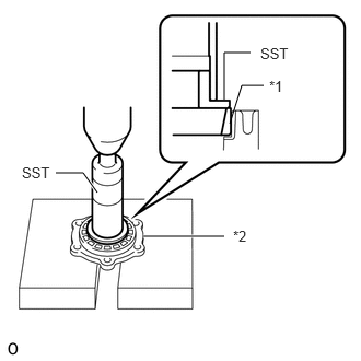
| *1 | Transfer Output Shaft Taper Roller Bearing (Outer Race) |
| *2 | Rear No. 1 Output Shaft Bearing Retainer |
Install the transfer output shaft shim to the rear No. 1 output shaft bearing retainer.
Using SST and a press, press in the transfer output shaft taper roller bearing (outer race) to the rear No. 1 output shaft bearing retainer.
- SST
-
09316-60011 (09316-00011, 09316-00031)
- HINT:
-
Replace both the outer race and bearing as a set.
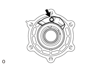
Install the No. 1 transfer oil receiver with the bolt.
- Torque:
- 8.82 N*m (90 kgf*cm, 78 in.*lbf)
36119A 24.INSTALL TRANSFER IDLER GEAR TRANSFER OIL RECEIVER
Clean and degrease the bolt and the installation hole.
Apply adhesive to 2 or 3 threads on the ends of the bolt.
- Adhesive:
-
Toyota Genuine Adhesive 1324, Three Bond 1324 or equivalent
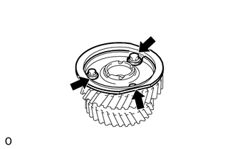
Install the transfer idler gear transfer oil receiver with the 3 bolts.
- Torque:
- 7.84 N*m (80 kgf*cm, 69 in.*lbf)
36221B 25.INSTALL TRANSFER IDLER GEAR BEARING
Apply MP grease to the 2 transfer idler gear bearings.
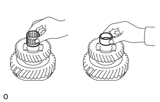
Install the 2 transfer idler gear bearings and transfer idler gear spacer.
36231E 26.INSTALL FRONT TRANSFER OUTPUT SHAFT NEEDLE ROLLER BEARING
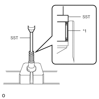
| *1 | Front Transfer Output Shaft Needle Roller Bearing |
Using SST and a press, press in a new front transfer output shaft needle roller bearing.
- SST
-
09950-60010 (09951-00250)
09950-70010 (09951-07200)
36314 27.INSTALL TRANSFER HIGH AND LOW SHIFT FORK SHAFT
Install the transfer high and low shift fork shaft to the No. 2 transfer gear shift fork.
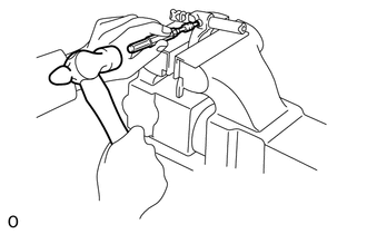
Using a pin punch and hammer, tap in the transfer shift fork slotted spring pin.
36203 28.INSTALL TRANSFER HIGH SPEED OUTPUT GEAR SUB-ASSEMBLY
Install the transfer high speed output gear sub-assembly to the rear transfer output shaft.
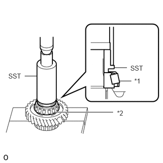
| *1 | Transfer Output Shaft Taper Roller Bearing (Inner Race) |
| *2 | Transfer High Speed Output Gear Sub-assembly |
Using SST and a press, press in the transfer output shaft taper roller bearing (Inner Race).
- SST
-
09316-60011 (09316-00011, 09316-00071)
- HINT:
-
Replace both the bearing and the outer race as a set.
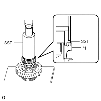
| *1 | Transfer Clutch Hub |
Using SST and a press, press in the transfer clutch hub.
- SST
-
09316-60011 (09316-00011, 09316-00071)
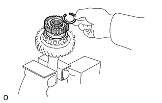
Select a snap ring that will allow minimum axial play.
- Standard Thickness:
-
Mark Thickness 11 2.30 to 2.35 mm (0.0906 to 0.0925 in.) 17 2.60 to 2.65 mm (0.1024 to 0.1043 in.)
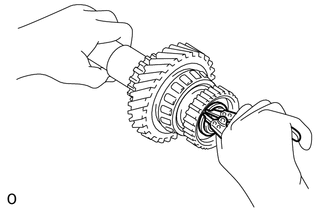
Using snap ring pliers, install a new transfer output shaft snap ring.
36235 29.INSTALL TRANSFER HIGH AND LOW CLUTCH SLEEVE
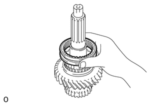
Install the transfer high and low clutch sleeve.
36204 30.INSTALL TRANSFER LOW SPEED OUTPUT GEAR SUB-ASSEMBLY
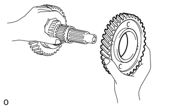
Install the transfer low speed output gear sub-assembly to the rear transfer output shaft.
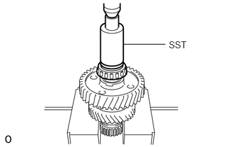
Using SST and a press, press in the transfer output shaft taper roller bearing.
- SST
-
09316-60011 (09316-00011, 09316-00071)
- HINT:
-
Replace both the bearing and the outer race as a set.
36203 31.INSPECT TRANSFER HIGH SPEED OUTPUT GEAR THRUST CLEARANCE
36204 32.INSPECT TRANSFER LOW SPEED OUTPUT GEAR THRUST CLEARANCE
36203 33.INSPECT TRANSFER HIGH SPEED OUTPUT GEAR RADIAL CLEARANCE
36204 34.INSPECT TRANSFER LOW SPEED OUTPUT GEAR RADIAL CLEARANCE
35.INSTALL FRONT TRANSFER CASE
Clean and degrease the bolt and the installation hole.
Apply adhesive to 2 or 3 threads on the ends of the bolt.
- Adhesive:
-
Toyota Genuine Adhesive 1324, Three Bond 1324 or equivalent
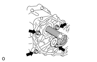
Install a new transfer case gasket and front transfer case with the 4 bolts.
- Torque:
- 63.7 N*m (650 kgf*cm, 47 ft.*lbf)
36134 36.INSTALL FRONT OUTPUT SHAFT BEARING RETAINER
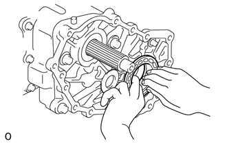
Install the front output shaft bearing retainer.
36225 37.INSTALL TRANSFER IDLER GEAR SHAFT
Coat a new O-ring with gear oil and install it to the transfer idler gear shaft front side groove.
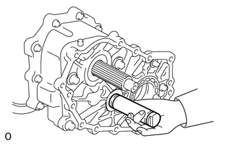
Install the transfer idler gear shaft to the front transfer case.
36221 38.INSTALL TRANSFER IDLER GEAR
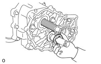
Install the transfer idler gear side thrust washer.
- HINT:
-
Be sure that the protruding part of the washer fits in the case groove.
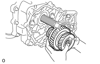
Install the transfer idler gear.
Coat a new O-ring with gear oil and install it to the transfer idler shaft rear side groove.
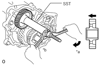
36212 39.INSTALL TRANSFER INPUT GEAR
| *a | Turn |
| *b | Hold |

|
Front Side |
Using SST, install the transfer input gear.
- SST
-
09309-36100
36251 40.INSTALL TRANSFER INPUT SHAFT SPACER
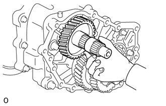
Install the transfer input shaft spacer to the transfer input shaft.
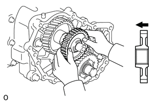
36215 41.INSTALL POWER TAKE-OFF DRIVE GEAR
|
|
Front Side |
Install the power take-off drive gear.
36212G 42.INSTALL REAR TRANSFER INPUT SHAFT RADIAL BALL BEARING
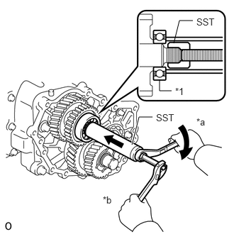
| *1 | Rear Transfer Input Shaft Radial Ball Bearing |
| *a | Turn |
| *b | Hold |
Using SST, install the rear transfer input shaft radial ball bearing.
- SST
-
09309-36100
43.INSTALL OUTPUT SHAFT ASSEMBLY
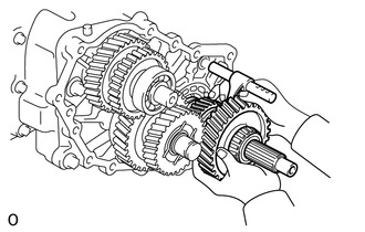
Install the high and low shift fork shaft assembly to the output shaft assembly.
Install the output shaft assembly and high and low shift fork shaft assembly to the front transfer case.
44.INSTALL REAR TRANSFER CASE
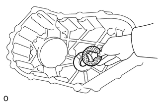
Using MP grease, stick the transfer idler gear side thrust washer to the rear transfer case.
- HINT:
-
Be sure that the protruding part of the washer fits in the case groove.
Install a new transfer case gasket to the rear transfer case.
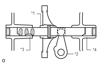
| *1 | High and Low Shift Fork Shaft Assembly |
| *2 | High and Low Shift Inner Lever Sub-assembly |
| *3 | Rear Transfer Case |
| *4 | Front Transfer Case |
While aligning the cutout of the high and low shift fork shaft assembly and high and low shift inner lever sub-assembly, install the rear transfer case.
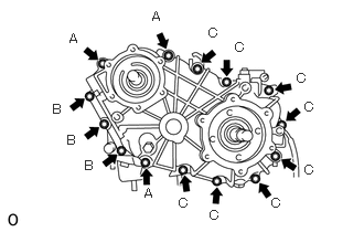
Install the rear transfer case with the 14 bolts.
- Torque:
- for bolt A : 66 N*m (673 kgf*cm, 49 ft.*lbf)
- for bolt B and bolt C : 39 N*m (398 kgf*cm, 29 ft.*lbf)
- Standard Bolt Length:
-
Item Specified Condition Bolt (A) 93 mm (3.6614 in.) Bolt (B) 35 mm (1.3780 in.) Bolt (C) 40 mm (1.5748 in.)
36275 45.INSTALL SHIFT DETENT BALL SPRING PLUG
Clean and degrease the bolt and the installation hole.
Apply adhesive to 2 or 3 threads on the ends of the bolt.
- Adhesive:
-
Toyota Genuine Adhesive 1324, Three Bond 1324 or equivalent
for Direct Shift Type:
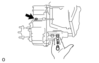
Install the 2 shift detent ball compression springs and 2 shift detent balls.
Install the 2 shift detent ball spring plugs.
- Torque:
- 44.1 N*m (450 kgf*cm, 33 ft.*lbf)
for Vacuum Shift Type:
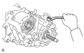
Install the shift detent ball compression spring and shift detent ball.
Install the shift detent ball spring plug.
- Torque:
- 44.1 N*m (450 kgf*cm, 33 ft.*lbf)
36726 46.INSTALL TRANSFER GEAR LOCK PLATE
Install the transfer gear lock plate with the bolt.
- Torque:
- 20.58 N*m (210 kgf*cm, 15 ft.*lbf)
33481P 47.INSTALL TRANSFER SPEEDOMETER DRIVE GEAR
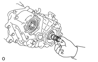
Install the transfer output shaft spacer, transfer speedometer drive gear and speedometer drive gear plate washer.
48.INSPECT OUTPUT SHAFT BEARING PRELOAD
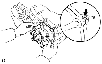
| *a | Rib |
Align the rib with the rear transfer case.
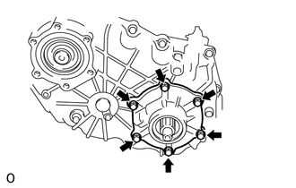
Install the rear No. 1 output shaft bearing retainer with the 6 bolts.
- Torque:
- 34.3 N*m (350 kgf*cm, 25 ft.*lbf)
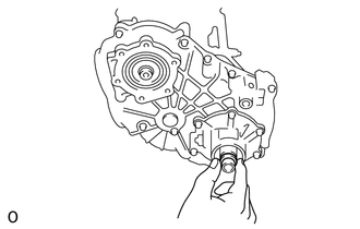
Temporarily install a new transfer output shaft nut.
Shift the outer lever of the transfer high and low shift lever to the N position.
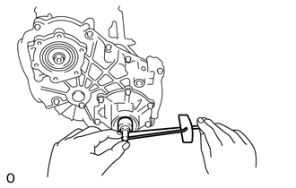
Using a torque wrench, measure the preload of the output shaft bearing.
- Preload (at starting):
- New bearing:
-
1.5 to 2.4 N*m (15 to 24 kgf*cm, 13 to 21 in.*lbf)
- Used bearing:
-
0.7 to 1.2 N*m (7 to 12 kgf*cm, 7 to 10 in.*lbf)
If the preload is not within specification, remove the outer race of the rear output shaft rear bearing.
- Standard Shim Thickness:
-
Mark Thickness Mark Thickness 0 0.15 mm (0.0059 in.) 10 1.00 mm (0.0394 in.) 4 0.40 mm (0.0157 in.) 11 1.10 mm (0.0433 in.) 5 0.50 mm (0.0197 in.) 12 1.20 mm (0.0472 in.) 6 0.60 mm (0.0236 in.) 13 1.30 mm (0.0512 in.) 7 0.70 mm (0.0276 in.) 14 1.40 mm (0.0551 in.) 8 0.80 mm (0.0315 in.) 15 1.50 mm (0.0591 in.) 9 0.90 mm (0.0354 in.) - -
- HINT:
-
·
Decrease the thickness of the shim if the preload is more than the specification, and increase the thickness of the shim if the preload is less than the specification.
·The preload will change about 1.0 N*m (10 kgf*cm, 9 in.*lbf) with each shim thickness.
Remove the transfer output shaft nut.
36132 49.REMOVE REAR NO. 1 OUTPUT SHAFT BEARING RETAINER
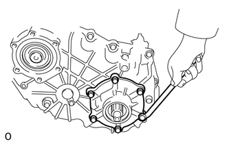
Remove the 6 bolts and rear No. 1 output shaft bearing retainer.
36132 50.INSTALL REAR NO. 1 OUTPUT SHAFT BEARING RETAINER
Clean and degrease the bolt and the installation hole.
Apply adhesive to 2 or 3 threads on the ends of the bolt.
- Adhesive:
-
Toyota Genuine Adhesive 1324, Three Bond 1324 or equivalent
| *a | Rib |
Place a new output shaft bearing retainer gasket on the rear transfer case.
Align the rib with the rear transfer case.
Install the rear No. 1 output shaft bearing retainer with the 6 bolts.
- Torque:
- 34.3 N*m (350 kgf*cm, 25 ft.*lbf)
36104B 51.INSTALL TRANSFER OUTPUT SHAFT DUST DEFLECTOR
Install the transfer output shaft dust deflector.
36104D 52.INSTALL TRANSFER OUTPUT SHAFT NUT
Install the transfer output shaft plate washer.
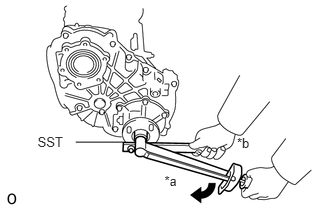
| *a | Turn |
| *b | Hold |
Using SST to hold the rear transfer output shaft companion flange, install the transfer output shaft nut.
- SST
-
09330-00021
- Torque:
- 127.4 N*m (1299 kgf*cm, 94 ft.*lbf)
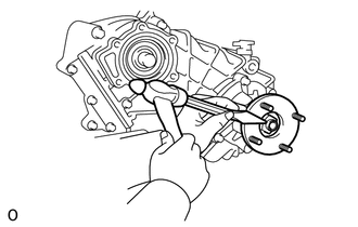
Using a chisel and hammer, stake the transfer output shaft nut.
36211B 53.INSTALL TRANSFER INPUT SHAFT NUT
Shift the outer lever of the transfer high and low shift lever to the H2 or L4 position.
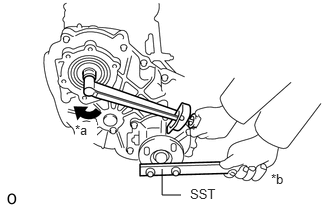
| *a | Turn |
| *b | Hold |
Using SST to hold the rear output shaft companion flange, install a new transfer input shaft nut.
- SST
-
09330-00021
- Torque:
- 127.4 N*m (1299 kgf*cm, 94 ft.*lbf)
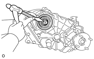
Using a chisel and hammer, stake the transfer input shaft nut.
36122 54.INSTALL NO. 2 TRANSFER CASE COVER
Clean and degrease the bolt and the installation hole.
Apply adhesive to 2 or 3 threads on the ends of the bolt.
- Adhesive:
-
Toyota Genuine Adhesive 1324, Three Bond 1324 or equivalent
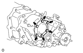
Install a new transfer cover gasket and the No. 2 transfer case cover with the 6 bolts.
- Torque:
- 15.19 N*m (155 kgf*cm, 11 ft.*lbf)
36124 55.INSTALL TRANSFER POWER TAKE-OFF COVER
Clean and degrease the bolt labeled A and the installation hole.
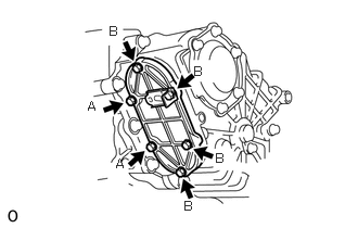
Apply adhesive to 2 or 3 threads on the ends of the bolts labeled A.
- Adhesive:
-
Toyota Genuine Adhesive 1324, Three Bond 1324 or equivalent
Install a new power take-off cover gasket, bracket and power take-off cover with the 6 bolts.
- Torque:
- for Bolt A : 16.66 N*m (170 kgf*cm, 12 ft.*lbf)
- for Bolt B : 19.11 N*m (195 kgf*cm, 14 ft.*lbf)
33403D 56.INSTALL SPEEDOMETER DRIVEN HOLE COVER SUB-ASSEMBLY (w/ ABS)
Coat a new O-ring with gear oil and install it to the speedometer driven hole cover sub-assembly.
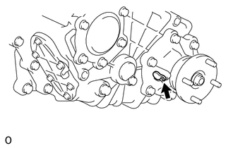
Install the speedometer driven hole cover sub-assembly with the bolt.
- Torque:
- 16 N*m (163 kgf*cm, 12 ft.*lbf)
33403 57.INSTALL SPEEDOMETER DRIVEN GEAR SUB-ASSEMBLY (w/o ABS)
Coat a new O-ring with gear oil and install it to the speedometer driven gear sub-assembly.
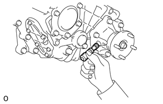
Install the speedometer driven gear sub-assembly with the lock plate and bolt.
- Torque:
- 16 N*m (163 kgf*cm, 12 ft.*lbf)
84222 58.INSTALL NO. 1 TRANSFER INDICATOR SWITCH (L4 POSITION) (w/ ABS)
84222 59.INSTALL NO. 1 TRANSFER INDICATOR SWITCH (4WD POSITION)