INTERIOR PANELS / TRIM INSTRUMENT PANEL SAFETY PAD REMOVAL
CAUTION / NOTICE / HINT
- HINT:
-
·
Use the same procedure for RHD and LHD vehicles.
·The procedure listed below is for LHD vehicles.
PROCEDURE

 1. TABLE OF BOLT, SCREW AND NUT
- HINT:
-
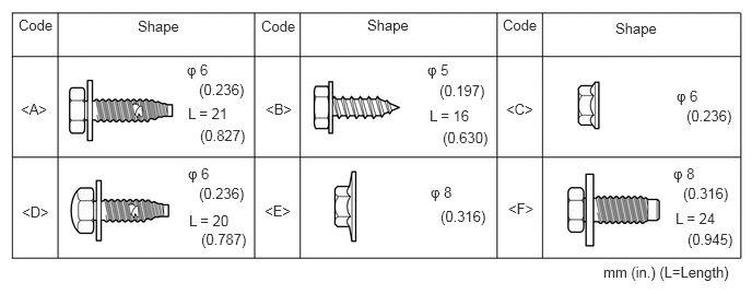
All bolts, screws, and clips relevant to installing and removing the instrument panel are shown along with their alphabet code in the table below.
2. PRECAUTION
- NOTICE:
-
After turning the ignition switch off, waiting time may be required before disconnecting the cable from the battery terminal. Therefore, make sure to read the disconnecting the cable from the battery terminal notice before proceeding with work.
-
Click hereGeneral>INTRODUCTION>REPAIR INSTRUCTION>PRECAUTION
3.DISCONNECT CABLE FROM NEGATIVE BATTERY TERMINAL
- CAUTION:
-
Wait at least 90 seconds after disconnecting the cable from the negative (-) battery terminal to disable the SRS system.
- NOTICE:
-
When disconnecting the cable, some systems need to be initialized after the cable is reconnected.
-
Click hereGeneral>INTRODUCTION>REPAIR INSTRUCTION>INITIALIZATION
84140 4.REMOVE HEADLIGHT DIMMER SWITCH ASSEMBLY
58811B 5.REMOVE CONSOLE BOX
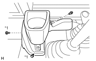
| *1 | Bolt <D> |
Remove the 2 bolts <D>, clip and front console box.
55480D 6.REMOVE LOWER INSTRUMENT PANEL FINISH PANEL ASSEMBLY
w/o Knee Airbag:
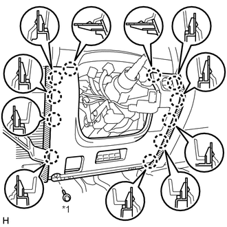
| *1 | Bolt <B> |

|
Protective Tape |
Put protective tape around the lower instrument panel finish panel assembly.
Remove the bolt <B>.
Using moulding remover B, detach the 11 claws and remove the lower instrument panel finish panel assembly.
- HINT:
-
If switches or the manual idle up cable is attached to the lower instrument panel finish panel assembly, disconnect each connector and the manual idle up cable before removing the lower instrument panel finish panel assembly.
w/ Driver Side Knee Airbag:
Put protective tape around the lower instrument panel finish panel assembly.
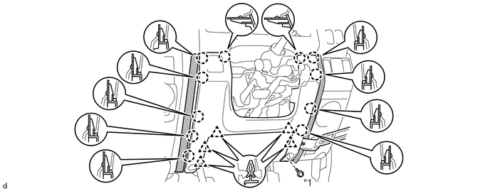
| *1 | Bolt <B> | - | - |
|
|
Protective Tape | - | - |
Remove the bolt <B>.
Using moulding remover B, detach the 11 claws and 5 clips and remove the lower instrument panel finish panel assembly.
- HINT:
-
If switches is attached to the lower instrument panel finish panel assembly, disconnect each connector before removing the lower instrument panel finish panel assembly.
73900 7.REMOVE LOWER NO. 1 INSTRUMENT PANEL AIR BAG ASSEMBLY (w/ Driver Side Knee Airbag)
55411G 8.REMOVE NO. 1 INSTRUMENT CLUSTER FINISH PANEL
|
|
Protective Tape |
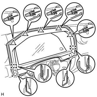
Put protective tape around the No. 1 instrument cluster finish panel.
Detach the 2 claws, 2 guides and 5 clips, and remove the No. 1 instrument cluster finish panel.
55421B 9.REMOVE UPPER INSTRUMENT CLUSTER FINISH PANEL
| *1 | Bolt <B> |
|
|
Protective Tape |
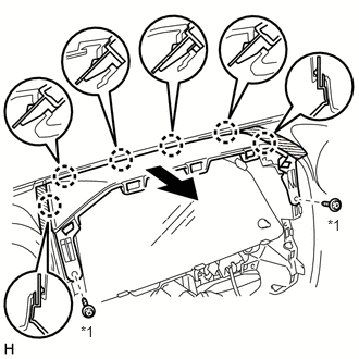
Put protective tape around the upper instrument cluster finish panel.
Remove the 2 bolts <B>.
Detach the 6 claws and remove the upper instrument cluster finish panel.
83100 10.REMOVE COMBINATION METER ASSEMBLY
55409F 11.REMOVE NO. 2 INSTRUMENT PANEL SPEAKER PANEL SUB-ASSEMBLY
| *1 | Bolt <B> |
|
|
Protective Tape |
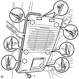
Put protective tape around the No. 2 instrument panel speaker panel sub-assembly.
Remove the bolt <B>.
Using moulding remover B, detach the 6 claws and 2 guides.
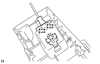
Detach the claw and 2 guides and disconnect the hood lock control cable and remove the No. 2 instrument panel speaker panel sub-assembly.
55446A 12.REMOVE NO. 1 SWITCH HOLE BASE
|
|
Protective Tape |
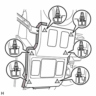
Put protective tape around the No. 1 switch hole base.
Using moulding remover B, detach the 6 clips and remove the No. 1 switch hole base.
- HINT:
-
If switches are attached to the No. 1 switch hole base, disconnect each connector before removing the No. 1 switch hole base.
55550 13.REMOVE GLOVE COMPARTMENT DOOR ASSEMBLY
| *a | Hinge |
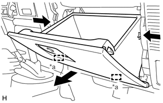
Push in the sides of the glove compartment door assembly to release the 2 stoppers and open the glove compartment door assembly until it is horizontal.
Pull the glove compartment door assembly toward the rear of the vehicle to detach the 2 hinges and remove the glove compartment door assembly.
55041B 14.REMOVE NO. 1 INSTRUMENT PANEL BOX DOOR SUB-ASSEMBLY (w/o Front Passenger Airbag)
|
|
Protective Tape |
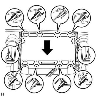
Put protective tape around the No. 1 instrument panel box door sub-assembly.
Using moulding remover B, detach the 10 claws and remove the No. 1 instrument panel box door sub-assembly.
73970A 15.REMOVE INSTRUMENT PANEL PASSENGER AIRBAG ASSEMBLY (w/ Front Passenger Airbag)
55434A 16.REMOVE LOWER INSTRUMENT FINISH PANEL SUB
| *1 | Bolt <B> |
w/o Assist Grip:
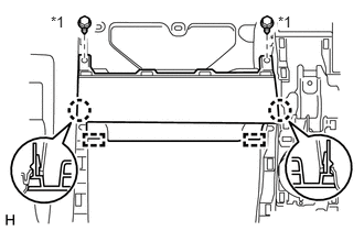
Remove the 2 bolts <B>.
Detach the 2 claws and 2 guides, and remove the lower instrument finish panel sub.
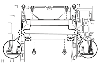
| *1 | Bolt <B> |
w/ Assist Grip:
Remove the 4 bolts and 2 bolts <B>.
Detach the 2 claws and 2 guides, and remove the lower instrument finish panel sub.
55329B 17.REMOVE NO. 4 INSTRUMENT PANEL STAY (w/ Assist Grip)
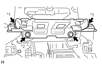
| *1 | Bolt <B> |
| *2 | Bolt <F> |
Remove the 2 bolts <B> and 2 bolts <F> and No. 4 instrument panel stay.
74670 18.REMOVE INSTRUMENT ASSIST GRIP ASSEMBLY (w/ Assist Grip)
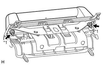
| *1 | Nut <E> |
Remove the 2 nuts <E> and instrument assist grip assembly.
55433B 19.REMOVE LOWER NO. 2 INSTRUMENT PANEL FINISH PANEL (w/ Assist Grip)
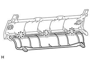
Detach the 3 claws and remove the lower No. 2 instrument panel finish panel.
55408F 20.REMOVE NO. 1 INSTRUMENT PANEL SPEAKER PANEL SUB-ASSEMBLY
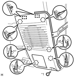
| *1 | Bolt <B> |
|
|
Protective Tape |
Put protective tape around the No. 1 instrument panel speaker panel sub-assembly.
Remove the bolt <B>
Using moulding remover B, detach the 6 claws and 2 guides, and remove the No. 1 instrument panel speaker panel sub-assembly.
86160 21.REMOVE FRONT NO. 1 SPEAKER ASSEMBLY
55452A 22.REMOVE NO. 2 INSTRUMENT PANEL BOX
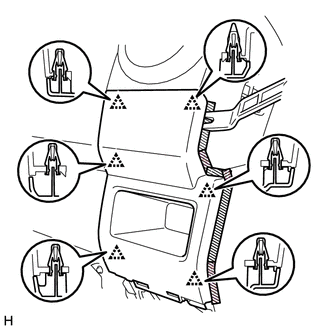
|
|
Protective Tape |
Put protective tape around the No. 2 instrument panel box.
Using moulding remover B, detach the 6 clips and remove the No. 2 instrument panel box.
55412D 23.REMOVE CENTER INSTRUMENT CLUSTER FINISH PANEL
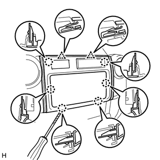
|
|
Protective Tape |
Put protective tape around the center instrument cluster finish panel.
Using a screwdriver, detach the 6 claws and 2 clips.
- HINT:
-
Tape the screwdriver tip before use.
Disconnect the connector and remove the center instrument cluster finish panel.
55522B 24.REMOVE RADIO TUNER OPENING COVER (w/o Audio)
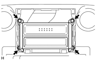
Remove the 2 screws, 2 bolts and radio tuner opening cover.
86120 25.REMOVE RADIO RECEIVER ASSEMBLY (w/ Audio)
74110 26.REMOVE INSTRUMENT PANEL ASH RECEPTACLE ASSEMBLY
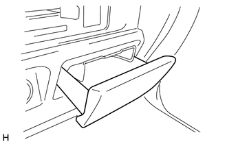
Remove the instrument panel ash receptacle assembly.
55413D 27.REMOVE CENTER LOWER INSTRUMENT CLUSTER FINISH PANEL
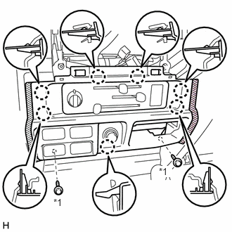
| *1 | Bolt <B> |
|
|
Protective Tape |
Put protective tape around the center lower instrument cluster finish panel.
Remove the 2 bolts <B>.
Detach the 7 claws.
Disconnect the connector and remove the center lower instrument cluster finish panel.
55910 28.REMOVE HEATER OR BOOST VENTILATOR CONTROL ASSEMBLY (w/ Air Conditioning System)
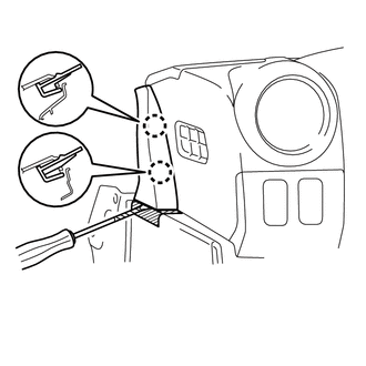
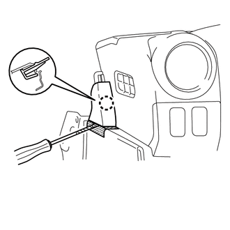
55356B 29.REMOVE INSTRUMENT PANEL PLATE LH
|
|
Protective Tape |
for Fixed Glass Type:
Put protective tape around the instrument panel plate LH.
Using a screwdriver, detach the 2 claws and remove the instrument panel plate LH.
- HINT:
-
Tape the screwdriver tip before use.
|
|
Protective Tape |
except Fixed Glass Type:
Put protective tape around the instrument panel plate LH.
Using a screwdriver, detach the claw and remove the instrument panel plate LH.
- HINT:
-
Tape the screwdriver tip before use.
55355B 30.REMOVE INSTRUMENT PANEL PLATE RH
- HINT:
-
Use the same procedure described for the LH side.
55318C 31.REMOVE INSTRUMENT SIDE PANEL LH
|
|
Protective Tape |
for Fixed Glass Type:
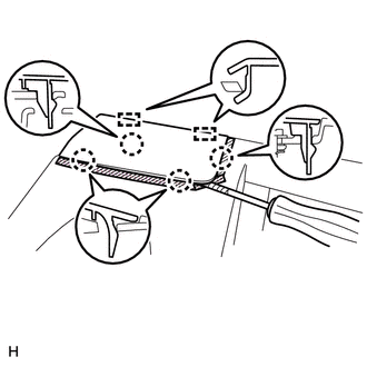
Put protective tape around the instrument side panel LH.
Using a screwdriver, detach the 4 claws and 2 guides, and remove the instrument side panel LH.
- HINT:
-
Tape the screwdriver tip before use.
|
|
Protective Tape |
for Fixed Glass Type:
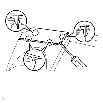
Put protective tape around the instrument side panel LH.
Using a screwdriver, detach the 4 claws and remove the instrument side panel LH.
- HINT:
-
Tape the screwdriver tip before use.
55317A 32.REMOVE INSTRUMENT SIDE PANEL RH
- HINT:
-
Use the same procedure described for the LH side.
55301 33.REMOVE INSTRUMENT PANEL SUB-ASSEMBLY
Disconnect the connector and detach each clamp.
Remove the 8 bolts <A>, 2 bolts <B> and nut <C>.
Detach the 4 guides and remove the instrument panel sub-assembly.
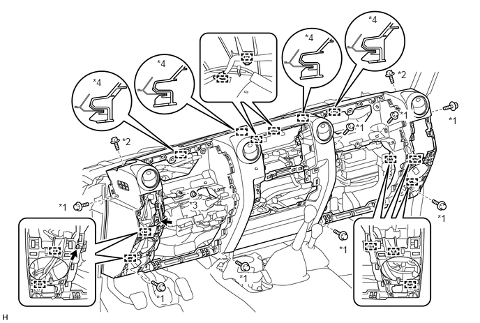
| *1 | Bolt <A> | *2 | Bolt <B> |
| *3 | Nut <C> | *4 | Guide |
34.REMOVE GLOVE COMPARTMENT DOOR LOCK CYLINDER ASSEMBLY
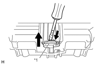
| *1 | Stopper |
|
|
Protective Tape |
Using a screwdriver, push the stopper of the glove compartment door lock cylinder as shown in the illustration and remove the glove compartment door lock cylinder assembly in the direction of the arrow.
- HINT:
-
Tape the screwdriver tip before use.