HEATING / AIR CONDITIONING AIR CONDITIONING UNIT REMOVAL
CAUTION / NOTICE / HINT
- HINT:
-
·
Use the same procedure for RHD and LHD vehicles.
·The procedure listed below is for LHD vehicles.
PROCEDURE

 1.RECOVER REFRIGERANT FROM REFRIGERATION SYSTEM
88712 2.REMOVE NO. 1 COOLER REFRIGERANT SUCTION HOSE (except Sub-cool Accelerator)
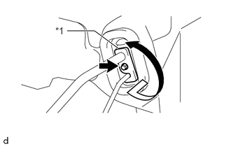
| *1 | Plate |
Remove the bolt and rotate the hook connector as shown in the illustration.
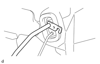
Disconnect the No. 1 cooler refrigerant suction hose.
Remove the O-ring from the No. 1 cooler refrigerant suction hose.
- NOTICE:
-
Seal the openings of the disconnected parts using vinyl tape to prevent the entry of moisture and foreign matter.
88716C 3.REMOVE COOLER REFRIGERANT LIQUID PIPE C (except Sub-cool Accelerator)
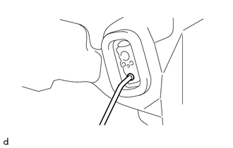
Disconnect the cooler refrigerant liquid pipe C.
Remove the O-ring from the cooler refrigerant liquid pipe C.
- NOTICE:
-
Seal the openings of the disconnected parts using vinyl tape to prevent the entry of moisture and foreign matter.
88710E 4.DISCONNECT AIR CONDITIONER TUBE AND ACCESSORY ASSEMBLY (for Sub-cool Accelerator)
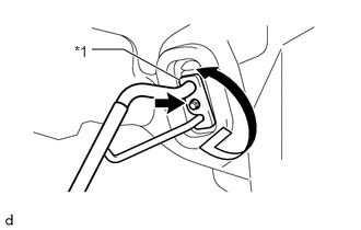
| *1 | Plate |
Remove the bolt and rotate the hook connector as shown in the illustration.
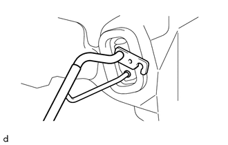
Disconnect the air conditioner tube and accessory assembly.
Remove the 2 O-rings from the air conditioner tube and accessory assembly.
- NOTICE:
-
Seal the openings of the disconnected parts using vinyl tape to prevent the entry of moisture and foreign matter.
85192 5.REMOVE WINDSHIELD WIPER ARM COVER
6.REMOVE WINDSHIELD WIPER ARM AND BLADE ASSEMBLY LH
7.REMOVE WINDSHIELD WIPER ARM AND BLADE ASSEMBLY RH
55781F 8.REMOVE COWL TOP VENTILATOR LOUVER
55792E 9.REMOVE NO. 2 HEATER AIR DUCT HOLE COVER
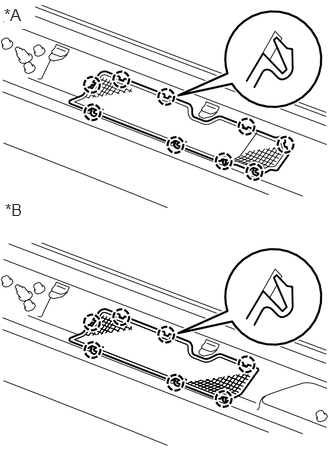
| *A | except Canvas Top |
| *B | for Canvas Top |
except Canvas Top:
Detach the 9 claws and remove the No. 2 heater air duct hole cover.
for Canvas Top:
Detach the 7 claws and remove the No. 2 heater air duct hole cover.
55301 10.REMOVE INSTRUMENT PANEL SUB-ASSEMBLY
11.REMOVE STEERING COLUMN ASSEMBLY
55834B 12.REMOVE NO. 2 INSTRUMENT PANEL REGISTER CONNECTOR
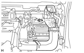
Remove the 2 clips and No. 2 instrument panel register connector together with the No. 5 heater to register duct.
55837C 13.REMOVE CENTER HEATER TO REGISTER SUB DUCT
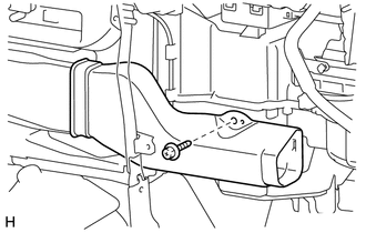
Remove the screw and center heater to register sub duct.
55833D 14.REMOVE NO. 1 INSTRUMENT PANEL REGISTER CONNECTOR
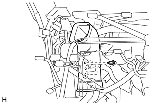
Remove the 2 clips and No. 1 instrument panel register connector.
55306A 15.REMOVE NO. 1 INSTRUMENT PANEL BRACE SUB-ASSEMBLY
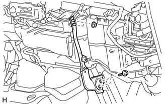
w/o Driver Side knee Airbag:
Remove the 2 nuts, 2 bolts and No. 1 instrument panel brace sub-assembly.
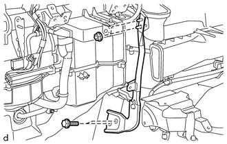
w/ Driver Side knee Airbag:
Remove the 2 nuts, 2 bolts and No. 1 instrument panel brace sub-assembly.
55307C 16.REMOVE NO. 2 INSTRUMENT PANEL BRACE SUB-ASSEMBLY
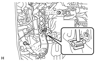
w/o Driver Side knee Airbag:
Detach the 2 claws and remove the instrument panel wire.
for 1GR-FE, for 1VD-FTV:
Detach the 2 claws and remove the DLC3 connector.
Remove the 2 nuts, 2 bolts and No. 2 instrument panel brace sub-assembly.
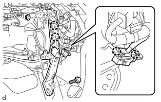
w/ Driver Side knee Airbag:
Detach the 2 claws and remove the instrument panel wire.
Detach the 2 claws and remove the DLC3 connector.
Remove the 2 nuts, 2 bolts and No. 2 instrument panel brace sub-assembly.
88650 17.REMOVE COOLER STABILIZER AMPLIFIER ASSEMBLY
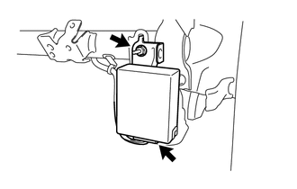
Disconnect the connector.
Remove the nut and cooler stabilizer amplifier assembly.
18.REMOVE DOOR CONTROL RECEIVER (w/ Wireless Door Lock System)
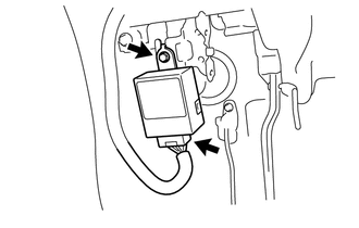
Remove the bolt and door control receiver.
Disconnect the connector.
28520 19.REMOVE PREHEATING TIMER ASSEMBLY (for 1HZ, w/o EGR)
89551 20.REMOVE EMISSION CONTROL ECU (for 1HZ, w/ EGR)
55331 21.REMOVE INSTRUMENT PANEL REINFORCEMENT
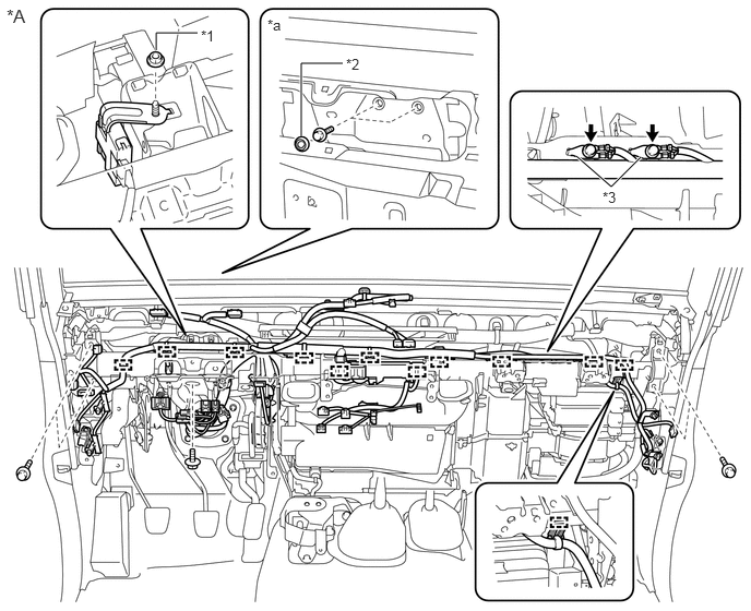
| *A | w/o Driver Side knee Airbag | - | - |
| *1 | Nut | *2 | Grommet |
| *3 | Ground Wire | - | - |
| *a | Engine Room Side | - | - |
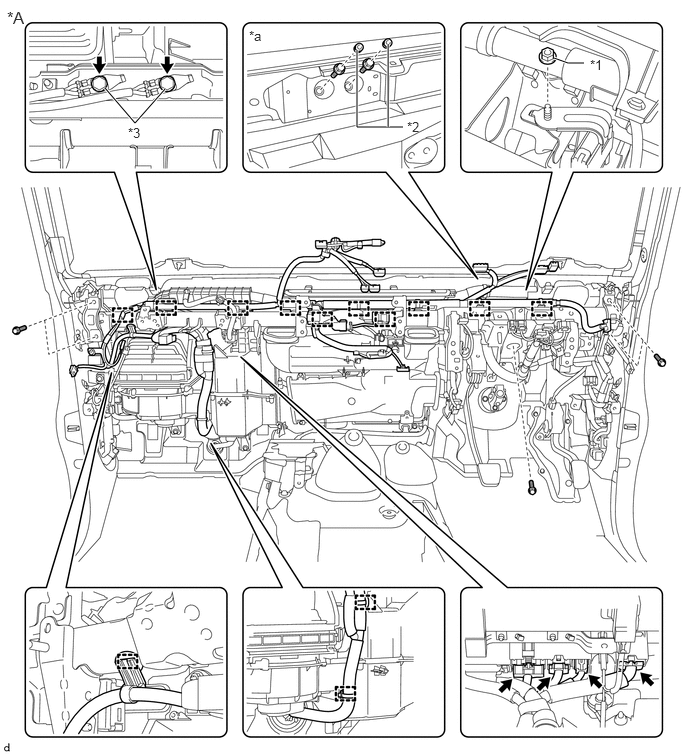
| *A | w/ Driver Side knee Airbag | - | - |
| *1 | Nut | *2 | Grommet |
| *3 | Ground Wire | - | - |
| *a | Engine Room Side | - | - |
Disconnect the connectors.
Remove the 2 grommets and 2 bolts from the engine room side.
Remove the 2 bolts and disconnect the 2 ground wires.
Detach the clamps and disconnect the instrument panel wire.
Remove the 5 bolts, nut and instrument panel reinforcement.
88510 22.REMOVE COOLER UNIT ASSEMBLY
Remove the No. 1 cooler unit drain hose.
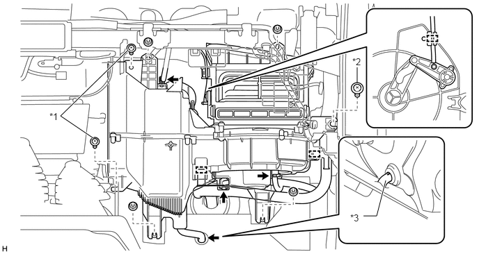
| *1 | Screw | *2 | Bolt |
| *3 | No. 1 Cooler Unit Drain Hose | - | - |
Remove the 4 nuts, 2 screws and bolt.
Disconnect the clamps, connectors and air inlet damper control cable sub-assembly.
Remove the cooler unit assembly.