DOOR / HATCH FRONT DOOR REASSEMBLY
CAUTION / NOTICE / HINT
- HINT:
-
·
Use the same procedure for RHD and LHD vehicle.
·The procedure listed below is for LHD vehicles.
·Use the same procedure for the RH and LH side.
·The procedure listed below is for the LH side.
·A bolt without a torque specification is shown in the standard bolt chart.
Click hereGeneral>SPECIFICATIONS>STANDARD BOLT>SPECIFIED TORQUE FOR STANDARD BOLTS
PROCEDURE

 67862 1.INSTALL FRONT DOOR WEATHERSTRIP LH (except Canvas Top)
Attach the 22 clips to install the weatherstrip.
68610 2.INSTALL FRONT DOOR CHECK ASSEMBLY
Apply MP grease to the sliding areas of the front door check assembly.
Install the door check to the door panel with the 2 bolts.
- Torque:
- 5.0 N*m (51 kgf*cm, 44 in.*lbf)
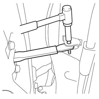
Using a brass bar and hammer, tap the door check pin into the body.
69320 3.INSTALL FRONT DOOR LOCK ASSEMBLY LH
69120A 4.INSTALL FRONT DOOR LOCK ACTUATOR ASSEMBLY LH (w/ Power Door Lock, Type B)
69310 5.INSTALL FRONT DOOR LOCK ASSEMBLY RH (w/ Double Inside Handles)
69220 6.INSTALL FRONT DOOR OUTSIDE HANDLE ASSEMBLY LH
Install the 2 bolts to the front door outside handle assembly LH.
- Torque:
- 8.0 N*m (82 kgf*cm, 71 in.*lbf)
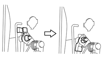
Attach the snap and connect the control link to the front door outside handle assembly LH as shown in the illustration.
69052 7.INSTALL FRONT DOOR LOCK CYLINDER ASSEMBLY LH
Install the front door lock cylinder assembly LH.
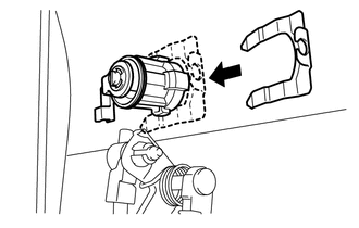
Install the plate.
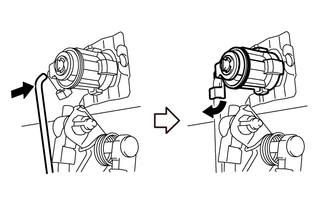
Attach the snap to the front door lock cylinder assembly LH as shown in the illustration.
69604A 8.INSTALL FRONT DOOR LOCK REMOTE CONTROL ROD SUB-ASSEMBLY LH
Attach the 2 claws to install the holder.
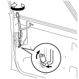
Install the front door lock remote control rod sub-assembly LH as shown in the illustration.
69712A 9.INSTALL FRONT DOOR LOCK REMOTE CONTROL LINK LH
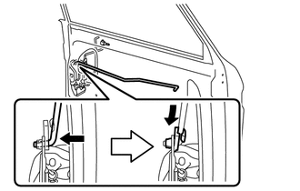
Install the front door lock remote control link LH to the front door lock assembly as shown in the illustration.
68143A 10.INSTALL FRONT DOOR NO. 2 GLASS RUN (w/o Vent Window)
Install the front door No. 2 glass run to the front door front lower frame sub-assembly LH.
67404F 11.INSTALL FRONT DOOR REAR LOWER FRAME SUB-ASSEMBLY LH (for Canvas Top)
Install the 2 bolts to the front door rear lower frame sub-assembly LH.
67404F 12.INSTALL FRONT DOOR REAR LOWER FRAME SUB-ASSEMBLY LH (except Canvas Top)
Attach the guide and install the bolt to the front door rear lower frame sub-assembly LH.
67504A 13.INSTALL FRONT DOOR DIVISION BAR SUB-ASSEMBLY LH (w/ Vent Window)
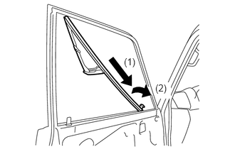
Install the front door division bar sub-assembly LH as indicated by the arrows in the order shown in the illustration.
Install the 3 screws and front door division bar sub-assembly LH.
68142A 14.INSTALL FRONT DOOR SIDE GLASS RUN (for Canvas Top)
Install the front door side glass run.
67482A 15.INSTALL FRONT DOOR FRONT LOWER FRAME SEAL LH (w/o Vent Window, except Canvas Top)
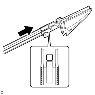
Install the front door front lower frame seal to the front door front lower frame sub-assembly LH as shown in the illustration.
67402F 16.INSTALL FRONT DOOR FRONT LOWER FRAME SUB-ASSEMBLY LH (w/o Vent Window, except Canvas Top)
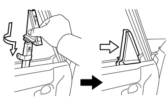
Install the front door front lower frame sub-assembly LH in the direction indicated by the arrow in the illustration.
Lift up the weatherstrip, and then install the 2 screws.
Install the front door front lower frame sub-assembly LH with the 2 bolts.
67402F 17.INSTALL FRONT DOOR FRONT LOWER FRAME SUB-ASSEMBLY LH (for Canvas Top)
Install the 2 bolts to the front door front lower frame sub-assembly LH.
67042 18.INSTALL FRONT DOOR WINDOW FRAME SUB-ASSEMBLY LH (for Canvas Top)
Install the 5 bolts to the front door window frame sub-assembly LH.
68193C 19.INSTALL FRONT DOOR FRONT BELT SEAL LH (for Canvas Top)
Install the screw to the front door front belt seal LH.
67864B 20.INSTALL FRONT DOOR NO. 2 WEATHERSTRIP LH (for Canvas Top)
Attach the 22 clips to install the weatherstrip.
67862 21.INSTALL FRONT DOOR WEATHERSTRIP LH (for Canvas Top)
Install the 2 screws to the front door weatherstrip LH.
68210C 22.INSTALL FRONT DOOR OUTER GLASS WEATHERSTRIP ASSEMBLY LH
85720A 23.INSTALL FRONT POWER WINDOW REGULATOR MOTOR ASSEMBLY LH (w/ Power Window)
69802 24.INSTALL FRONT DOOR WINDOW REGULATOR SUB-ASSEMBLY LH (w/ Power Window)
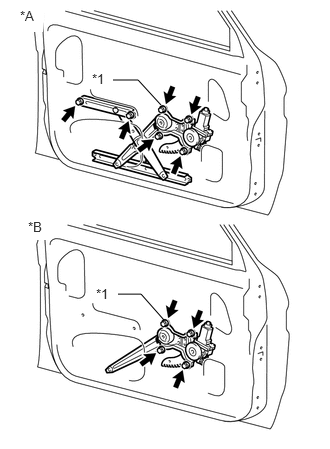
| *A | w/o Vent Window |
| *B | w/ Vent Window |
| *1 | Temporary Bolt |
Apply MP grease to the sliding and rotating areas of the front door window regulator sub-assembly LH.
Temporarily install the temporary bolt to the front door window regulator sub-assembly LH.
w/o Vent Window:
Install the front door window regulator sub-assembly LH with the 5 bolts, and then tighten the temporary bolt.
- Torque:
- 8.0 N*m (82 kgf*cm, 71 in.*lbf)
- HINT:
-
Tighten the bolts in the order shown in the illustration.
- NOTICE:
-
Be careful not to drop the front door window regulator as it may become damaged.
w/ Vent Window:
Install the front door window regulator sub-assembly LH with the 3 bolts, and then tighten the temporary bolt.
- Torque:
- 8.0 N*m (82 kgf*cm, 71 in.*lbf)
- HINT:
-
Tighten the bolts in the order shown in the illustration.
- NOTICE:
-
Be careful not to drop the front door window regulator as it may become damaged.
Connect the connector.
69802 25.INSTALL FRONT DOOR WINDOW REGULATOR SUB-ASSEMBLY LH (w/o Power Window)
Apply MP grease to the sliding and rotating areas of the front door window regulator sub-assembly LH.
w/o Vent Window:
Install the front door window regulator sub-assembly LH with the 5 bolts.
w/ Vent Window:
Install the front door window regulator sub-assembly LH with the 3 bolts.
68102 26.INSTALL FRONT DOOR GLASS SUB-ASSEMBLY LH (w/ Power Window)
w/ Vent Window:
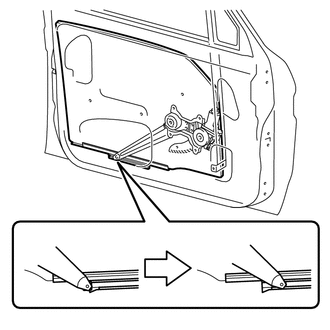
Install the front door glass sub-assembly LH to the front door window regulator assembly as shown in the illustration.
- NOTICE:
-
Be careful not to damage the glass.
w/o Vent Window:
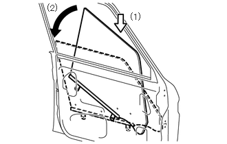
Install the front door glass sub-assembly LH as indicated by the arrows in the order shown in the illustration.
- NOTICE:
-
Be careful not to damage the glass.
Install the 2 bolts.
- Torque:
- 8.0 N*m (82 kgf*cm, 71 in.*lbf)
- NOTICE:
-
Be careful when removing the bolts as the glass may fall and become damaged.
68102 27.INSTALL FRONT DOOR GLASS SUB-ASSEMBLY LH (w/o Power Window)
w/ Vent Window:
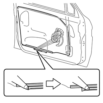
Install the front door glass sub-assembly LH to the front door window regulator assembly as shown in the illustration.
- NOTICE:
-
Be careful not to damage the glass.
w/o Vent Window:
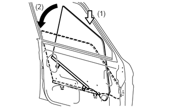
Install the front door glass sub-assembly LH as indicated by the arrows in the order shown in the illustration.
- NOTICE:
-
Be careful not to damage the glass.
Install the 2 bolts.
- Torque:
- 8.0 N*m (82 kgf*cm, 71 in.*lbf)
- NOTICE:
-
Be careful when removing the bolts as the glass may fall and become damaged.
68141 28.INSTALL FRONT DOOR GLASS RUN
Install the front door glass run.
68220A 29.INSTALL FRONT DOOR INNER GLASS WEATHERSTRIP ASSEMBLY LH
w/ Vent Window:
Attach the 5 claws to install the front door inner glass weatherstrip assembly LH.
w/ Vent Window:
Attach the 7 claws to install the front door inner glass weatherstrip assembly LH.
for Model Code #J76 Series, for Double Cab
Attach the 6 claws to install the front door inner glass weatherstrip assembly LH.
67832 30.INSTALL FRONT DOOR SERVICE HOLE COVER LH
Apply new butyl tape to the front door panel.
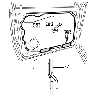
| *1 | Tape |
| *2 | Door Panel |
| *3 | Service Hole Cover |
Install the front door service hole cover.
- NOTICE:
-
·
When installing the service hole cover, pull out the links through the service hole cover.
·There should be no wrinkles or folds after attaching the service hole cover.
·After attaching the service hole cover, check the sealing quality.
Attach the clamp and 2 new grommets.
Install the tape, as shown in the illustration.
69205 31.INSTALL FRONT DOOR INSIDE HANDLE SUB-ASSEMBLY RH (w/ Double Inside Handles)
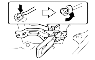
Connect the front door inside handle sub-assembly RH to the control link and install the front door inside handle sub-assembly RH.
Install the 2 screws.
69759V 32.INSTALL FRONT DOOR LOCK LINK SILENCER
Install the front door lock link silencer.
74220 33.INSTALL FRONT ARMREST ASSEMBLY LH (w/ Armrest, w/ Power Window)
Install the 5 screws to the front armrest assembly LH.
74231 34.INSTALL FRONT ARMREST UPPER BASE PANEL (w/ Double Inside Handles)
Install the 4 screws to the front armrest upper base panel.
67778 35.INSTALL FRONT DOOR TRIM POCKET LH (w/ Door Pocket)
Install the 5 screws to the front door trim pocket LH.
67602 36.INSTALL FRONT DOOR TRIM BOARD SUB-ASSEMBLY LH (w/ Armrest)
Attach the 14 clips to install the front door trim board sub-assembly LH.
w/o Power Window:
Install the 2 screws to the front armrest assembly LH.
w/ Power Window:
Install the 2 screws and 2 caps.
67602 37.INSTALL FRONT DOOR TRIM BOARD SUB-ASSEMBLY LH (for Canvas Top)
Attach the 14 clips to the front door trim board sub-assembly LH.
67702 38.INSTALL FRONT DOOR TRIM COVER SUB-ASSEMBLY LH (for Canvas Top)
Attach the guide to the front door trim cover sub-assembly LH.
Install the screw.
39.INSTALL POWER WINDOW REGULATOR MASTER SWITCH ASSEMBLY WITH FRONT DOOR ARMREST BASE PANEL (for Driver Side, w/ Power Window)
Connect the connector.
Attach the clip and 4 claws, and install the power window regulator master switch assembly with front door armrest base panel.
40.INSTALL POWER WINDOW REGULATOR SWITCH ASSEMBLY WITH FRONT DOOR ARMREST BASE PANEL (for Front Passenger Side, w/ Power Window)
Connect the connector.
w/ o Double Inside Handles:
Attach the clip and 4 claws, and install the power window regulator switch assembly with front door armrest base panel.
w/ Double Inside Handles:
Attach the 2 claws and install the power regulator switch assembly with front door armrest base panel.
69260 41.INSTALL FRONT DOOR WINDOW REGULATOR HANDLE ASSEMBLY (w/o Power Window)
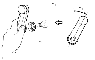
| *1 | Plate |
| *a | Front |
| *b | 30° |
With the door window fully closed, install the plate and regulator handle with the snap ring as shown in the illustration.
68278B 42.INSTALL DOOR INSIDE HANDLE BEZEL (w/ Double Inside Handles)
Install the screw to the door inside handle bezel.
69206B 43.INSTALL FRONT DOOR INSIDE HANDLE SUB-ASSEMBLY
Connect the front door inside handle sub-assembly LH to the control link and install the front door inside handle sub-assembly LH.
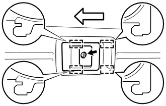

|
Screw |

|
Rearward |
Attach the 4 guides in the direction indicated by the arrow in the illustration.
Install the screw and front door inside handle sub-assembly.
74640C 44.INSTALL DOOR ASSIST GRIP ASSEMBLY LH (w/ Assist Grip)
Install the 2 screws and door assist grip assembly LH.
Attach the 4 claws and install the 2 caps.
45.INSTALL HOLE PLUG (for Canvas Top)
Install the 4 hole plugs.
87941 46.INSTALL OUTER REAR VIEW MIRROR GASKET LH
87940 47.INSTALL OUTER REAR VIEW MIRROR ASSEMBLY LH
48.CONNECT CABLE TO NEGATIVE BATTERY TERMINAL
- Torque:
- 5.4 N*m (55 kgf*cm, 48 in.*lbf)
49. INITIALIZATION AFTER RECONNECTING BATTERY TERMINAL
- HINT:
-
When disconnecting and reconnecting the battery, there is an automatic learning function that completes learning when the respective system is used.
-
Click hereGeneral>SETUP>WHEN DISCONNECTING OR RECONNECTING BATTERY TERMINAL>AUTOMATIC LEARNING CHART
50.CHECK POWER WINDOW CONTROL SYSTEM (w/ Power Window)
51.CHECK POWER DOOR LOCK CONTROL SYSTEM (w/ Power Door Lock)