LIGHTING (EXT) STOP LIGHT SWITCH INSTALLATION
CAUTION / NOTICE / HINT
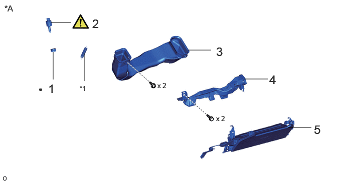
| Procedure | Part Name Code | 
|

|

|
|
|---|---|---|---|---|---|
| 1 | STOP LIGHT SWITCH MOUNTING ADJUSTER | 84345 | - | - | - |
| 2 | STOP LIGHT SWITCH ASSEMBLY | 84340 | ( ) |
- | - |
| 3 | NO. 2 HEATER TO REGISTER DUCT | 55844 | - | - | - |
| 4 | AIR DUCT SUB-ASSEMBLY | - | - | - | - |
| 5 | LOWER NO. 1 INSTRUMENT PANEL AIR BAG ASSEMBLY | 73900 | - | - | - |
| *A | for LHD | - | - |
| *1 | Spring | - | - |
| ● | Non-reusable part | - | - |
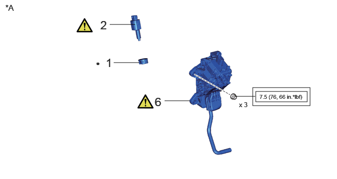
| Procedure | Part Name Code |
|
|
|
|
|---|---|---|---|---|---|
| 1 | STOP LIGHT SWITCH MOUNTING ADJUSTER | 84345 | - | - | - |
| 2 | STOP LIGHT SWITCH ASSEMBLY | 84340 | ()
|
- | - |
| 6 | ACCELERATOR PEDAL(WITH SENSOR) ROD ASSEMBLY | 78110K | ()
|
- | - |
| *A | for RHD | - | - |

|
Tightening torque for "Major areas involving basic vehicle performance such as moving/turning/stopping": N*m (kgf*cm, ft.*lbf) | - | - |
| ● | Non-reusable part | - | - |
PROCEDURE

 84345
1.INSTALL STOP LIGHT SWITCH MOUNTING ADJUSTER
84340
2.INSTALL STOP LIGHT SWITCH ASSEMBLY
for RHD:
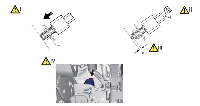
| *1 | Stop light switch mounting adjuster | - | - |
Insert the stop light switch assembly to the stop light switch mounting adjuster until the switch body slightly touches the brake pedal.
- NOTICE:
- ·
When inserting the stop light switch assembly, make sure not to engage the brake pedal.
·Operate it while supporting it with one hand so that the brake pedal does not move.
Turn the stop light switch assembly clockwise by approximately one fourth of a rotation.
- NOTICE:
- ·
When inserting the stop light switch assembly, make sure not to engage the brake pedal.
·Operate it while supporting it with one hand so that the brake pedal does not move.
·When turning the stop light switch assembly clockwise, do not exceed 1.5 N*m (15 kgf*cm, 1 ft.*lbf) turning torque.
Check the protrusion amount of the shaft.
- Standard:
a 0.5 to 2.6 mm (0.0197 to 0.1024 in.)
Connect the connector.
- NOTICE:
-
Check that the stop light does not illuminate with the brake pedal not depressed.
for LHD:
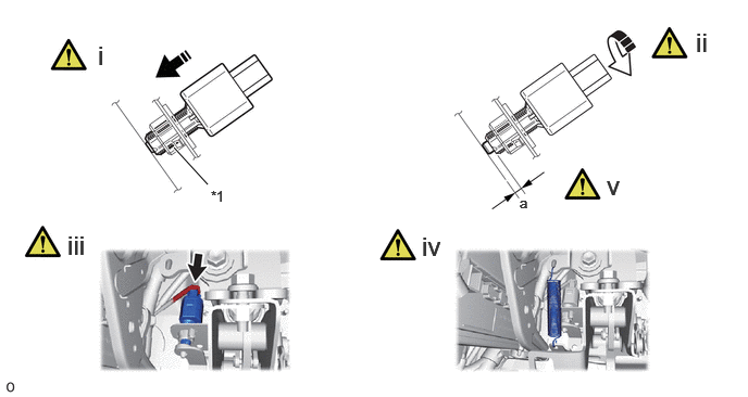
| *1 | Stop light switch mounting adjuster | - | - |
Insert the stop light switch assembly to the stop light switch mounting adjuster until the switch body slightly touches the brake pedal.
- NOTICE:
- ·
When inserting the stop light switch assembly, make sure not to engage the brake pedal.
·Operate it while supporting it with one hand so that the brake pedal does not move.
Turn the stop light switch assembly clockwise by approximately one fourth of a rotation.
- NOTICE:
- ·
When inserting the stop light switch assembly, make sure not to engage the brake pedal.
·Operate it while supporting it with one hand so that the brake pedal does not move.
·When turning the stop light switch assembly clockwise, do not exceed 1.5 N*m (15 kgf*cm, 1 ft.*lbf) turning torque.
Connect the connector.
Install the spring.
Check the protrusion amount of the shaft.
- Standard:
a 0.5 to 2.6 mm (0.0197 to 0.1024 in.)
- NOTICE:
-
Check that the stop light does not illuminate with the brake pedal not depressed.
55844
3.INSTALL NO. 2 HEATER TO REGISTER DUCT (for LHD)
4.INSTALL AIR DUCT SUB-ASSEMBLY (for LHD)
73900
5.INSTALL LOWER NO. 1 INSTRUMENT PANEL AIR BAG ASSEMBLY (for LHD)
78110K
6.INSTALL ACCELERATOR PEDAL(WITH SENSOR) ROD ASSEMBLY (for RHD)
|
|
Click here()
|