Q710 HYBRID TRANSMISSION / TRANSAXLE SHIFT CONTROL ECU REMOVAL
CAUTION / NOTICE / HINT
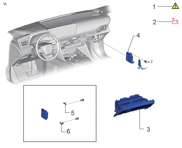
| Procedure | Part Name Code | 
|

|

|
|
|---|---|---|---|---|---|
| 1 | PRECAUTION | - | ( ) |
- | - |
| 2 | DISCONNECT CABLE FROM NEGATIVE AUXILIARY BATTERY TERMINAL | - | ()
|
- | - |
| 3 | GLOVE COMPARTMENT DOOR ASSEMBLY | 55550 | - | - | - |
| 4 | SHIFT CONTROL ECU | 894C1 | - | - | - |
| 5 | NO. 1 SHIFT CONTROL ECU BRACKET | 894C7 | - | - | - |
| 6 | NO. 2 SHIFT CONTROL ECU BRACKET | 894C8 | - | - | - |
| *A | for LHD | - | - |
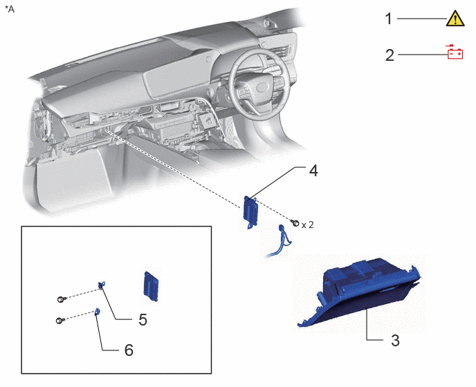
| Procedure | Part Name Code |
|
|
|
|
|---|---|---|---|---|---|
| 1 | PRECAUTION | - | ()
|
- | - |
| 2 | DISCONNECT CABLE FROM NEGATIVE AUXILIARY BATTERY TERMINAL | - | ()
|
- | - |
| 3 | GLOVE COMPARTMENT DOOR ASSEMBLY | 55550 | - | - | - |
| 4 | SHIFT CONTROL ECU | 894C1 | - | - | - |
| 5 | NO. 1 SHIFT CONTROL ECU BRACKET | 894C7 | - | - | - |
| 6 | NO. 2 SHIFT CONTROL ECU BRACKET | 894C8 | - | - | - |
| *A | for RHD | - | - |
CAUTION / NOTICE / HINT
The necessary procedures (adjustment, calibration, initialization, or registration) that must be performed after parts are removed and installed, or replaced during shift control ECU removal/installation are shown below.
| Replaced Part or Performed Procedure | Necessary Procedure | Effect/Inoperative Function when Necessary Procedurenot Performed | Link |
| Auxiliary battery terminal isdisconnected/reconnected | Memorize steering angle neutral point | Parking assist monitor system | ()
|
| Panoramic view monitor system | ()
|
||
| Shift Control ECU | Update ECU security key | Vehicle control history (RoB) are stored | ()
|
| Inspection after repair | ·
The P position switch blinks when the ignition switch is turned to ON or ON (READY) and the shift position is not in P. ·
The power source off automatic P function does not operate. ·
The shift position is not displayed on the meter until a shift change operation is performed. |
()
|
- HINT:
-
When the cable is disconnected/reconnected to the auxiliary battery terminal, systems temporarily stop operating. However, each system has a function that completes learning the first time the system is used.
- ·
Learning completes when vehicle is driven
Effect/Inoperative Function When Necessary Procedures are not Performed Necessary Procedures Link Lane tracing assist system Drive the vehicle straight ahead at 35 km/h (22 mph) or more for 5 seconds or more. ( )
Pre-collision system Adaptive high beam system
·Learning completes when vehicle is operated normally
Effect/Inoperative Function When Necessary Procedures are not Performed Necessary Procedures Link Air conditioning system After the ignition switch is turned to ON, the servo motor and expansion valve standard position is recognized. -
PROCEDURE

 1. PRECAUTION
|
|
|
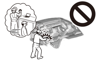
2.DISCONNECT CABLE FROM NEGATIVE AUXILIARY BATTERY TERMINAL
|
|
|
Turn the ignition switch off.
Check that the ODO meter display has turned off.
- HINT:
-
The ODO meter continues to display for 30 seconds after turning off. Therefore, allow sufficient time for the shift control ECU to enter sleep mode and for the sub-battery power supply to end. In addition to monitoring the sub-battery voltage directly, the only other method for checking on the vehicle is to use the ODO meter display.
Disconnect the cable from the negative (-) auxiliary battery terminal.
55550
3.REMOVE GLOVE COMPARTMENT DOOR ASSEMBLY
894C1
4.REMOVE SHIFT CONTROL ECU
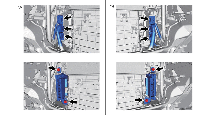
| *A | for LHD | *B | for RHD |
894C7
5.REMOVE NO. 1 SHIFT CONTROL ECU BRACKET
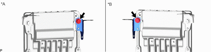
| *A | for LHD | *B | for RHD |
894C8
6.REMOVE NO. 2 SHIFT CONTROL ECU BRACKET
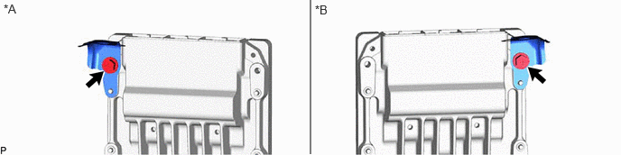
| *A | for LHD | *B | for RHD |