Q710 HYBRID TRANSMISSION / TRANSAXLE SHIFT CONTROL ECU INSTALLATION
CAUTION / NOTICE / HINT
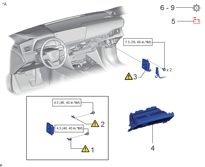
| Procedure | Part Name Code | 
|

|

|
|
|---|---|---|---|---|---|
| 1 | NO. 2 SHIFT CONTROL ECU BRACKET | 894C8 | ( ) |
- | - |
| 2 | NO. 1 SHIFT CONTROL ECU BRACKET | 894C7 | ()
|
- | - |
| 3 | SHIFT CONTROL ECU | 894C1 | ()
|
- | - |
| 4 | GLOVE COMPARTMENT DOOR ASSEMBLY | 55550 | - | - | - |
| 5 | CONNECT CABLE TO NEGATIVE AUXILIARY BATTERY TERMINAL | - | ()
|
- | - |
| 6 | CHECK AND CLEAR DTC | - | - | - | ()
|
| 7 | UPDATE ECU SECURITY KEY | - | - | - | ()
|
| 8 | CHECK SRS WARNING LIGHT | - | - | - | ()
|
| 9 | INITIALIZATION AFTER RECONNECTING BATTERY TERMINAL | - | - | - | ()
|
| *A | for LHD | - | - |

|
N*m (kgf*cm, ft.*lbf): Specified torque | - | - |
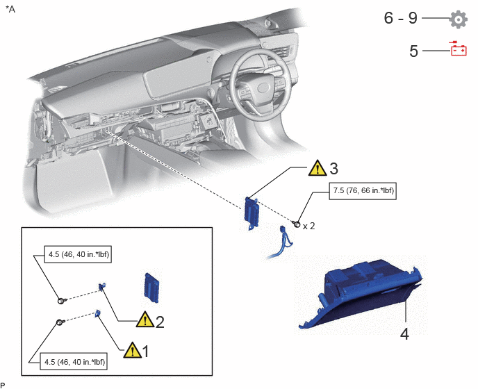
| Procedure | Part Name Code |
|
|
|
|
|---|---|---|---|---|---|
| 1 | NO. 2 SHIFT CONTROL ECU BRACKET | 894C8 | ()
|
- | - |
| 2 | NO. 1 SHIFT CONTROL ECU BRACKET | 894C7 | ()
|
- | - |
| 3 | SHIFT CONTROL ECU | 894C1 | ()
|
- | - |
| 4 | GLOVE COMPARTMENT DOOR ASSEMBLY | 55550 | - | - | - |
| 5 | CONNECT CABLE TO NEGATIVE AUXILIARY BATTERY TERMINAL | - | ()
|
- | - |
| 6 | CHECK AND CLEAR DTC | - | - | - | ()
|
| 7 | UPDATE ECU SECURITY KEY | - | - | - | ()
|
| 8 | CHECK SRS WARNING LIGHT | - | - | - | ()
|
| 9 | INITIALIZATION AFTER RECONNECTING BATTERY TERMINAL | - | - | - | ()
|
| *A | for RHD | - | - |
|
|
N*m (kgf*cm, ft.*lbf): Specified torque | - | - |
PROCEDURE

 894C8
1.INSTALL NO. 2 SHIFT CONTROL ECU BRACKET
|
|
|
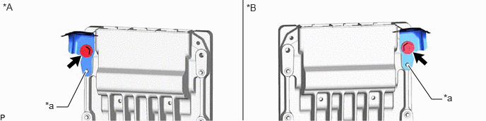
| *A | for LHD | *B | for RHD |
| *a | Align the protrusion of the No. 2 shift control ECU bracket with the cutout of the shift control ECU. | - | - |
- Torque:
- 4.5 N*m (46 kgf*cm, 40 in.*lbf)
894C7
2.INSTALL NO. 1 SHIFT CONTROL ECU BRACKET
|
|
|
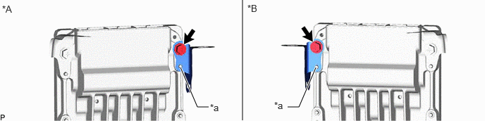
| *A | for LHD | *B | for RHD |
| *a | Align the protrusion of the No. 1 shift control ECU bracket with the cutout of the shift control ECU. | - | - |
- Torque:
- 4.5 N*m (46 kgf*cm, 40 in.*lbf)
894C1
3.INSTALL SHIFT CONTROL ECU
|
|
|
- Torque:
- 7.5 N*m (76 kgf*cm, 66 in.*lbf)
55550
4.INSTALL GLOVE COMPARTMENT DOOR ASSEMBLY
5.CONNECT CABLE TO NEGATIVE AUXILIARY BATTERY TERMINAL
6.CHECK AND CLEAR DTC
7. UPDATE ECU SECURITY KEY
8.CHECK SRS WARNING LIGHT
9. INITIALIZATION AFTER RECONNECTING BATTERY TERMINAL
Click hereGeneral>SETUP>WHEN DISCONNECTING OR RECONNECTING BATTERY TERMINAL>WORK PROCEDURE
- HINT:
-
When disconnecting and reconnecting the battery, there is an automatic learning function that completes learning when the respective system is used.
-
Click hereGeneral>SETUP>WHEN DISCONNECTING OR RECONNECTING BATTERY TERMINAL>AUTOMATIC LEARNING CHART
10. CONFIRMATION WORK AFTER REPLACING SHIFT CONTROL ECU
After replacing the shift control ECU, check for the following symptoms. If any of these symptoms exists, be sure to perform the following procedure starting from step b.
The P position switch blinks when the ignition switch is turned to ON or ON (READY) and the shift position is not in P.
The power source off automatic P function does not operate.
The shift position is not displayed on the meter until a shift change operation is performed.
Turn the ignition switch to ON.
Press the P position switch and change the shift position to P.
Turn the ignition switch to ON (READY).
Depress the brake pedal and operate the shift lever to change the shift position to D.
Check that the P position switch does not blink when the ignition switch is turned to ON or ON (READY), and the shift position is not in P.
- NOTICE:
-
If the P position switch is blinking, be sure to perform steps b. through e. again.