WIPER / WASHER WIPER AND WASHER SYSTEM TERMINALS OF ECU
CHECK WINDSHIELD WIPER MOTOR ASSEMBLY
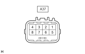
- HINT:
-
Since the windshield wiper motor assembly uses waterproof connectors, the voltage, resistance and waveform cannot be checked directly. The voltage, resistance and waveform are indicated for reference only.
Measure the voltage, resistance and waveform on the wire harness side connector according to the value(s) in the table below.
| Terminal No. (Symbol) | Terminal Description | Condition | Specified Condition |
|---|---|---|---|
| A37-1 (WSR+) - Body ground | Washer motor operation signal | Windshield washer motor and pump assembly not operating | Below 1 V |
| Windshield washer motor and pump assembly operating | 11 to 14 V | ||
| A37-2 (WSR-) - Body ground | Washer motor operation signal | Windshield washer motor and pump assembly not operating | Below 1 V |
| Windshield washer motor and pump assembly operating | 11 to 14 V | ||
| A37-3 (2S) - Body ground | Wiper HI operation signal | Windshield wiper motor assembly not operating | 11 to 14 V |
| Windshield wiper motor assembly HI operating | Below 1 V | ||
| A37-4 (GND) - Body ground | Ground | Always | Below 1 Ω |
| A37-5 (FWAB) - Body ground | Washer motor power supply | Ignition switch off | 11 to 14 V |
| A37-6 (+B) - Body ground | Wiper motor power supply | Ignition switch ON or within approximately 60 seconds of ignition switch being turned off | 11 to 14 V |
| Approximately 60 seconds have elapsed after ignition switch is turned off | Below 1 V | ||
| A37-7 (LIN) - Body ground | LIN communication signal | Ignition switch ON | Pulse generation |
| Ignition switch off | Below 1 V |
| Terminal No. (Symbol) | Terminal Description | Condition | Specified Condition |
|---|---|---|---|
| A37-4 (WSR+) - Body ground | Washer motor operation signal | Windshield washer motor and pump assembly not operating | Below 1 V |
| Windshield washer motor and pump assembly operating | 11 to 14 V | ||
| A37-3 (WSR-) - Body ground | Washer motor operation signal | Windshield washer motor and pump assembly not operating | Below 1 V |
| Windshield washer motor and pump assembly operating | 11 to 14 V | ||
| A37-2 (2S) - Body ground | Wiper HI operation signal | Windshield wiper motor assembly not operating | 11 to 14 V |
| Windshield wiper motor assembly HI operating | Below 1 V | ||
| A37-1 (GND) - Body ground | Ground | Always | Below 1 Ω |
| A37-8 (FWAB) - Body ground | Washer motor power supply | Ignition switch off | 11 to 14 V |
| A37-7 (+B) - Body ground | Wiper motor power supply | Ignition switch ON or within approximately 60 seconds of ignition switch being turned off | 11 to 14 V |
| Approximately 60 seconds have elapsed after ignition switch is turned off | Below 1 V | ||
| A37-6 (LIN) - Body ground | LIN communication signal | Ignition switch ON | Pulse generation |
| Ignition switch off | Below 1 V |
CHECK DRIVER SIDE JUNCTION BLOCK ASSEMBLY AND MAIN BODY ECU (MULTIPLEX NETWORK BODY ECU)
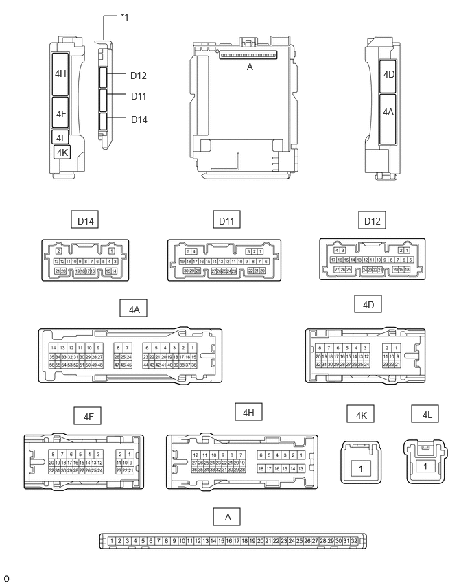
| *1 | Main Body ECU (Multiplex Network Body ECU) | - | - |
Remove the main body ECU (multiplex network body ECU) from the driver side junction block assembly.
Click herePower Source / Network>POWER DISTRIBUTION>MAIN BODY ECU>REMOVAL
Reconnect the driver side junction block assembly connectors.
Measure the voltage and resistance according to the value(s) in the table below.
| Terminal No. (Symbol) | Terminal Description | Condition | Specified Condition |
|---|---|---|---|
| A-11 (GND1) - Body ground | Ground | Always | Below 1 Ω |
| A-31 (BECU) - Body ground | Auxiliary battery power supply | Ignition switch off | 11 to 14 V |
| A-30 (ACC) - Body ground | ACC power supply | Ignition switch ACC | 11 to 14 V |
| Ignition switch off | Below 1 V | ||
| A-32 (IG) - Body ground | IG power supply | Ignition switch ON | 11 to 14 V |
| Ignition switch off | Below 1 V |
Install the main body ECU (multiplex network body ECU) to the driver side junction block assembly.
Click herePower Source / Network>POWER DISTRIBUTION>MAIN BODY ECU>INSTALLATION
Measure the voltage and check for pulses according to the value(s) in the table below.
| Terminal No. (Symbol) | Terminal Description | Condition | Specified Condition |
|---|---|---|---|
|
*: w/ Rear Camera Cleaner System |
|||
| D11-21 (WPS) - Body ground | Windshield wiper relay (WIPER NO. 1) power supply | Ignition switch ON or within approximately 60 seconds of ignition switch being turned off | 11 to 14 V |
| Approximately 60 seconds have elapsed after ignition switch is turned off | Below 1 V | ||
| D12-3 (LIN3) - Body ground | LIN communication line | Ignition switch ON | Pulse generation |
| D12-23 (RWSR) - Body ground* | Camera cleaner relay (LIDAR CLN RR/CAMERA CLN) power supply | Ignition switch ON, washer switch (CAMERA) and camera cleaner operating | Below 1 V |
| Ignition switch ON, washer switch (CAMERA WASH) and camera cleaner not operating | 11 to 14 V | ||