AUDIO / VIDEO ASC SYSTEM B1360 Speaker Circuit
DESCRIPTION
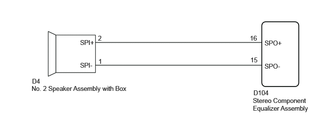
This DTC is stored when a connection malfunction, such as an open, is detected in the wire harness between the stereo component equalizer assembly and No. 2 speaker assembly with box.
| DTC No. | Detection Item | DTC Detection Condition | Trouble Area | DTC Output from | Priority |
|---|---|---|---|---|---|
| B1360 | Speaker Circuit | Open in the speaker circuit | ·
Harness or connector ·
No. 2 speaker assembly with box ·
Stereo component equalizer assembly |
ASC | A |
WIRING DIAGRAM
PROCEDURE
Using the GTS, perform the Active Test.
- Body Electrical > ASC > Active Test
-
Tester Display Measurement Item Control Range Diagnostic Note Sound ASC system ON or OFF -
- Body Electrical > ASC > Active Test
-
Tester Display Sound - 50004 365 1
- OK:
Sound is output.
- Result:
Proceed to OK NG
OK
NG
Click hereAudio / Visual / Telematics>AUDIO / VIDEO>ASC SPEAKER (for Instrument Panel)>INSPECTION
- Result:
Proceed to OK NG
OK
NG
Pre-procedure1
Disconnect the D104 stereo component equalizer assembly connector.
Disconnect the D4 No. 2 speaker assembly with box connector.
Procedure1
Measure the resistance according to the value(s) in the table below.
- Standard Resistance:
Tester Connection Condition Specified Condition Click Location & Routing(D104,D4)Location & Routingewd_type=routing;type=c,c;code=D104,D4
Click Connector(D104)Instrument Panel>Instrument Panel Wire>Stereo Component Equalizer Assemblyewd_type=component;type=c;code=D104;pinno=16,15
Click Connector(D4)Instrument Panel>Instrument Panel Wire>No. 2 Speaker with Box Assemblyewd_type=component;type=c;code=D4;pinno=2,1
D104-16(SPO+) - D4-2(SPI+) Always Below 1 Ω D104-15(SPO-) - D4-1(SPI-) Always Below 1 Ω D104-16(SPO+) or D4-2(SPI+) - Body ground Always 10 kΩ or higher D104-15(SPO-) or D4-1(SPI-) - Body ground Always 10 kΩ or higher
- Result:
Proceed to OK NG
Post-procedure1
None
OK
NG